Project Information
Description: Students will follow along with a tutorial and learn to design a 3D printable carabiner in CAD and then use FEA to analyze the performance of the design under stress. Students will use the insights gained from FEA to improve the strength and performance of their design.
Learning outcomes:
- Students will understand how stress affects 3D printed parts.
- Students will know the basics of how FEA can be applied to part design.
- Students will know what FEA is and its applications to mechanical engineering.
- Students will better understand how to apply their knowledge of mechanical stress to part design.
- Students will be able to use FEA to study part stresses.
Estimated Time: 5 hours or Less (Depending on previous knowledge)
Note:
What students will need:
- A computer with CAD that has a FEA Package (Fusion 360 is used in this tutorial)
Introduction
Project Goal
The goal of this project is to introduce part design, design optimization using FEA (Finite Element Analysis), design for manufacture, and iterative design. Giving examples of how to apply those skills to a carabiner, then challenging them to design their own carabiner.
Prior knowledge
This tutorial is designed for using Fusion 360. This tutorial is not designed to be a replacement for a more comprehensive introduction to Fusion 360 course, but I will be walking through everything at a basic level.
Fusion 360 is not the only CAD program you can use along with this guide. These concepts will translate to most programs on the market with a little know-how.
Needed Programs
CAD+FEA: Fusion 360 (or your choice)
Slicer: Cura (or your choice)
Designing a Carabiner
Let’s start designing a carabiner. Like most CAD projects, it is almost always best to start with a hand drawing of what you want your part to look like before you do anything on the computer. Hand drawings are a good way to quickly get your ideas down without needing dimensions or a detailed idea of what it will look line.
First, we need to understand the form and function of a carabiner, and the problem they are meant to solve. Like anything in engineering, before anything goes down in paper or CAD, the engineer needs to have a solid fundamental understanding of what they are designing. As these will be the guiding principles in how the part (piece, system, etc.) will be formed.
Whether it’s as simple as a carabiner or as complicated as a satellite, a solid understanding of the basics is the foundation for how engineers are able to do their jobs.
Function is the purpose of your design, the specific technical operations performed. As well as the reason you are building the product.
Form is the finalized structure of the device, product, and is the culmination of how the function is achieved.
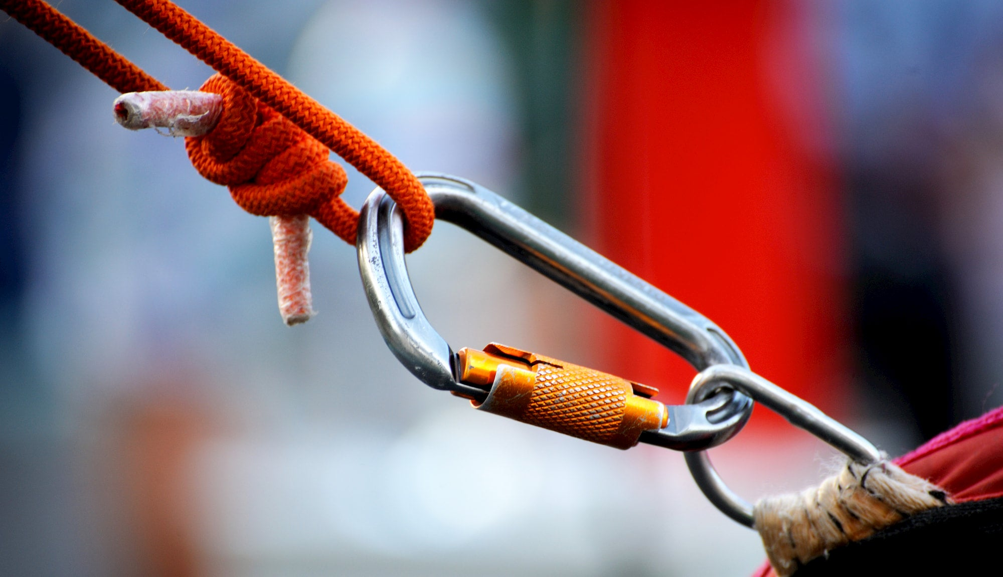
A standard carabiner is simple, and you probably have one lying around to look at as an example. The main function of a carabiner is to securely join different components together. These components usually come in the form of rope, cables, straps, pins, or other fixtures. The main feature of a carabiner that separates it from other types of shackles is an easily operated gate, allowing quick connecting and disconnecting of components.
With the function in mind, we can jump right to the form since
carabiners have been around for a long time. You probably have one
laying around to look at.
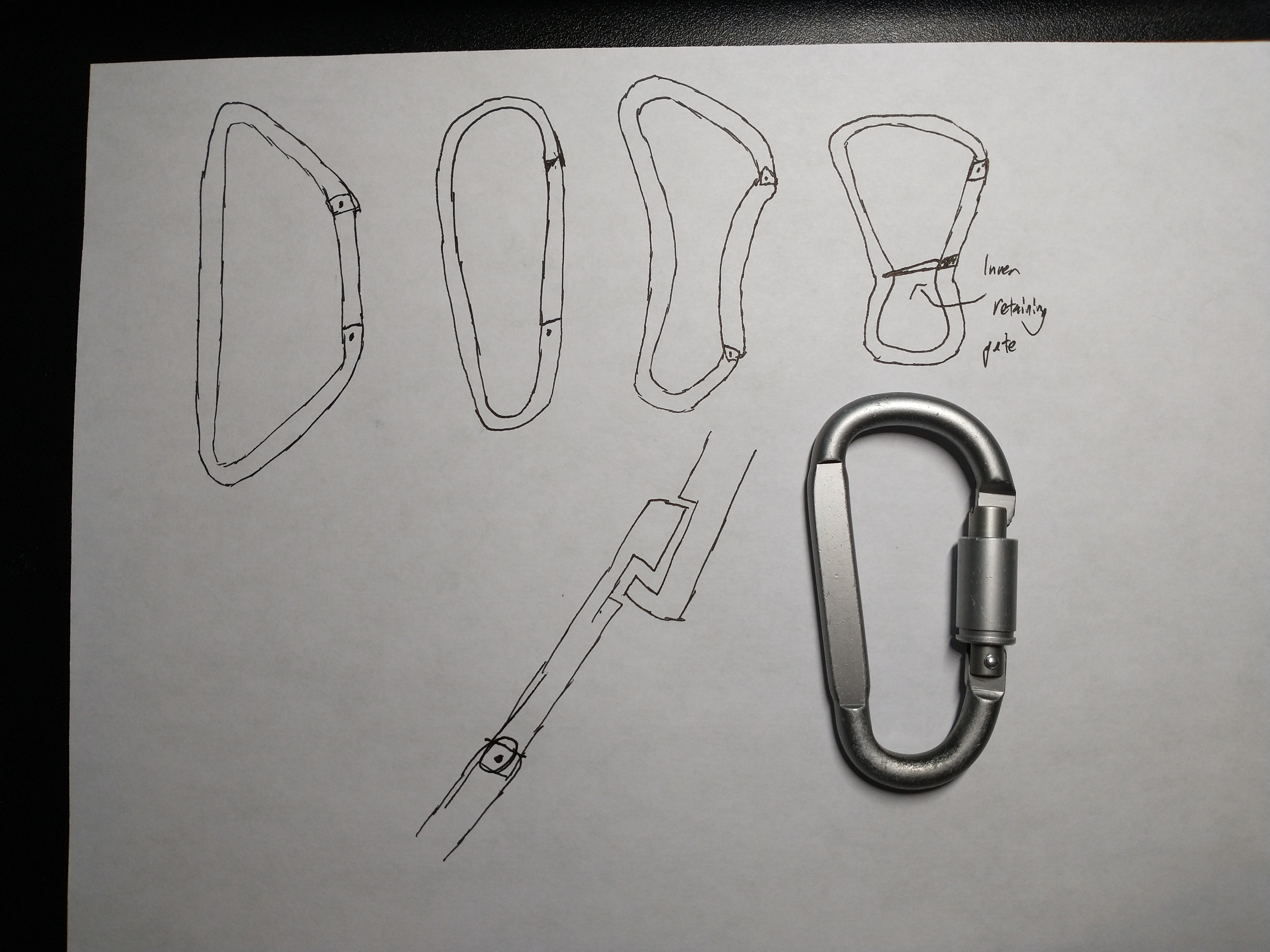
Next, it’s time to jump into a rough sketch. These are always the beginning of creating CAD designs. For this example, I aimed to include a few key parts. The first of which are what views you want, views in engineering drawings are how a three-dimensional part is broken up into 2-D drawings.
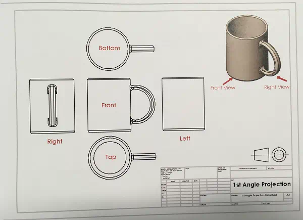
The front view should always be the view that shows the most detail of the part. For most parts you would want to include more views, or even an orthographic view (3-D), but since a carabiner is simple we only need one view to convey the main shape and functions of the carabiner.
In the sketch itself, another important feature it needs is noting rough dimensions, position of the gate, and also noting the radii of corners, and other features like the direction of motion
I decided to go with a simple pear shape over something like a ‘bent’ frame for simplicity. I will be going over the gate in more detail later, but I threw in sketch of that as well.
But whatever you have, let’s get out first sketch down in CAD.
CAD Introduction
See Here for Link to download Fusion 360 if you do not have it already. Create an account using your school email and fill out the required information. You may need to submit your school ID to get a educational license.
After opening Fusion 360, you should see a screen similar to this.
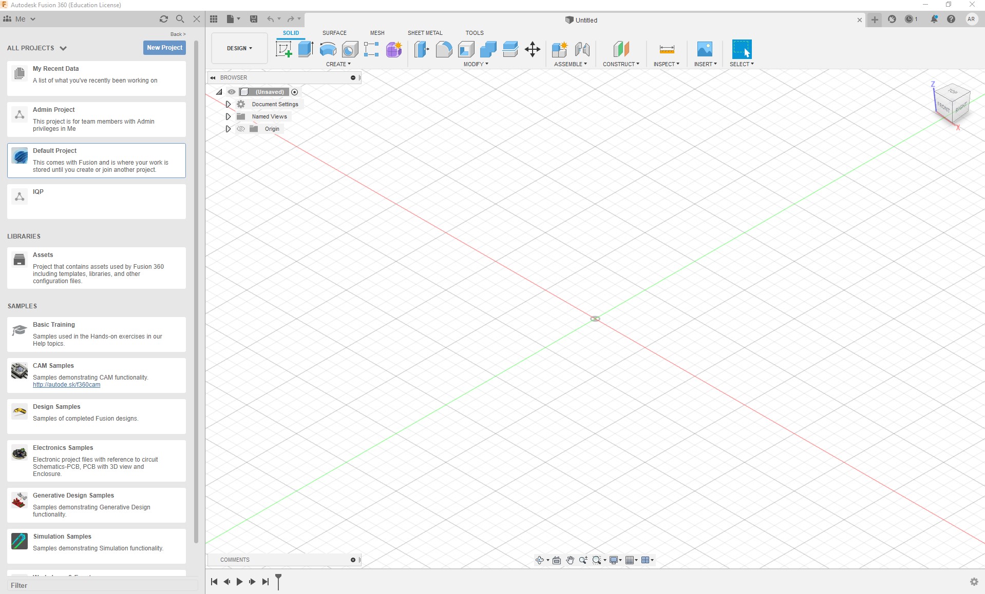
On the left side is the “Data Panel”, where you will see projects, create folders, save parts, and other features like sharing files with others.

On the right side of the screen is the Design Workspace, the virtual space where parts and assemblies are created. You should see a “Untitled” in the tab near the top of the window. Also along the top of the screen is the workspace, clicking on the down arrow nest to ‘Design’ will show all the available workspaces. Each workspace has a different function, feel free to explore each of these. For this section, we will only be using the Design workspace.
To the right of the workspace dropdown is the different toolbars available. The Solid is for solid modeling, and what we will be focusing on for our case.
Double click on “Default Project” and create a new folder for your Carabiner.
Once inside that folder, click save on the untitled part, give it a name and click save.
Now, we can start modeling. There are a wide range of different tools inside Fusion 360, and as such there are a multitude of different ways you can go about modeling your carabiner. To start I will be going over a simple extrusion, a straight forward method for you to start learning the methodology for creating parts.
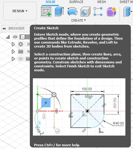
To start, click on the “Create Sketch” Button to enter sketch mode.

After clicking, the center of the design window will show you the different planes (X Y and Z) you can choose to sketch on. The white dot in the middle is the origin. To see what each plane is called (Aka named view) look at the view cube in the upper right side of the screen. After clicking on the plane you want, you will be automatically oriented to perpendicular to the plane.
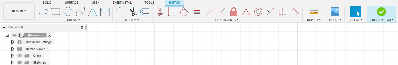
Once here, you will see the “Sketch” toolbar appear across the top of your window.
In this toolbar, you can create the features that make up your sketch. The sketch tool works similarly to sketching by hand, you can create lines, circles, rectangles, and other features one by one and combine them together to create your final sketch.
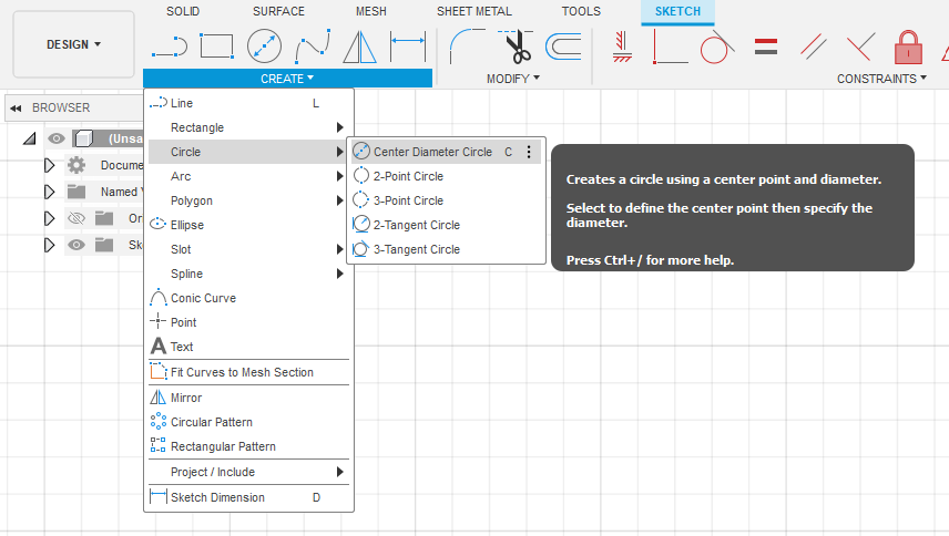
Click the arrow next to Create, and mouse down over the different options. Hovering over each provides a short description of how to use it and can save you lots of time.
Looking at my sketch, I started off by adding some construction geometry. Construction geometry, denoted by a dashed line, is treated like any normal sketch but is only there to help you better define the rest of your sketch.
Clicking on the line tool (Hotkey L), first click on the origin, then move your cursor up a little bit, hovering near the green line (denoting the Y axis) your second point should ‘Snap’ to being vertical. Before clicking to confirm placement, move your mouse to the left and right. When snapping to a grid or line, you will notice that a small blue symbol pops up to the side of the line. This symbol is a constraint that is automatically applied when snapping, a vertical constraint in this case. Constraints can also be added later down the line, click somewhere on the side so the line isn’t snapped vertically.
After placing, click on the line (highlighted blue) and then click on the “Horizontal/Vertical” constraint. Fusion will apply the Horizontal or Vertical constraint to whatever orientation the line is closest to.
Holding control while selecting a specific part of a sketch allows you to apply constraints to different sketch components together.
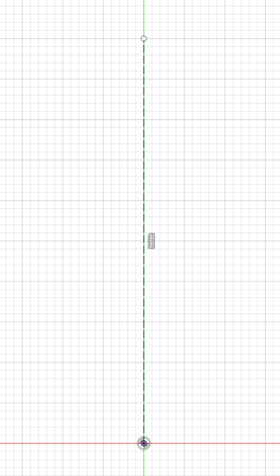
After your line is placed, we need to make is construction geometry, to do this click on the line and press x (Hotkey for changing to/from construction geometry). Your line should now look like the photo above.
You will see that the line is black, but with a white circle on one end. The black color means that the line is geometrically constrained (Fixed to the origin, and Vertical), while the white circle on the second point means that the length of the line is not constrained (whereas a light blue line means it is not geometrically constrained).
To fully constrain the line, click on the “Sketch Dimension” tool, click on the line, move the dimension note off the line slightly so you can see it. Finally, enter a dimension into the box and press enter.
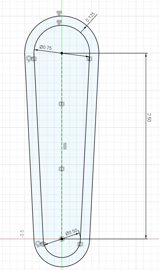
Congrats! You have now created a fully defined line. For creating the rest of the sketches for your carabiner, you should follow the same strategy. Let me go through how I did this for the outline.
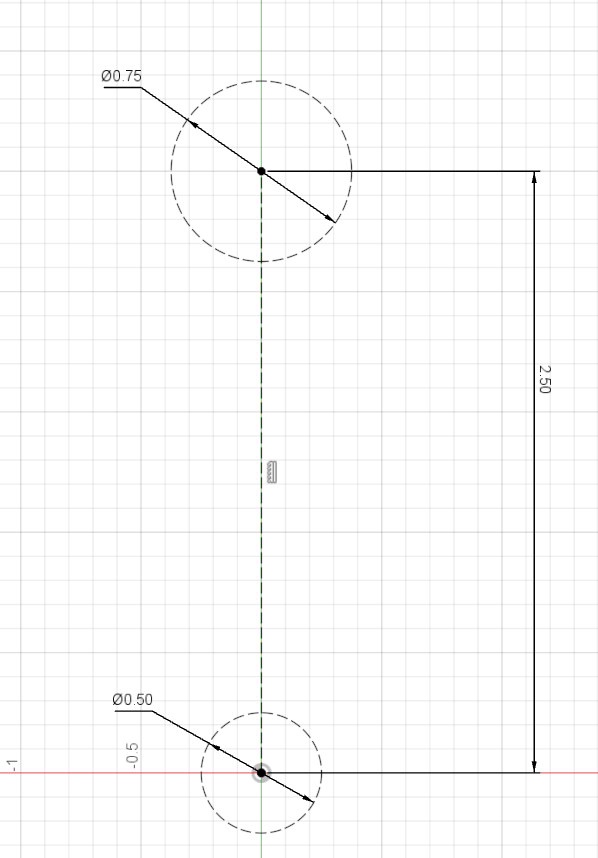
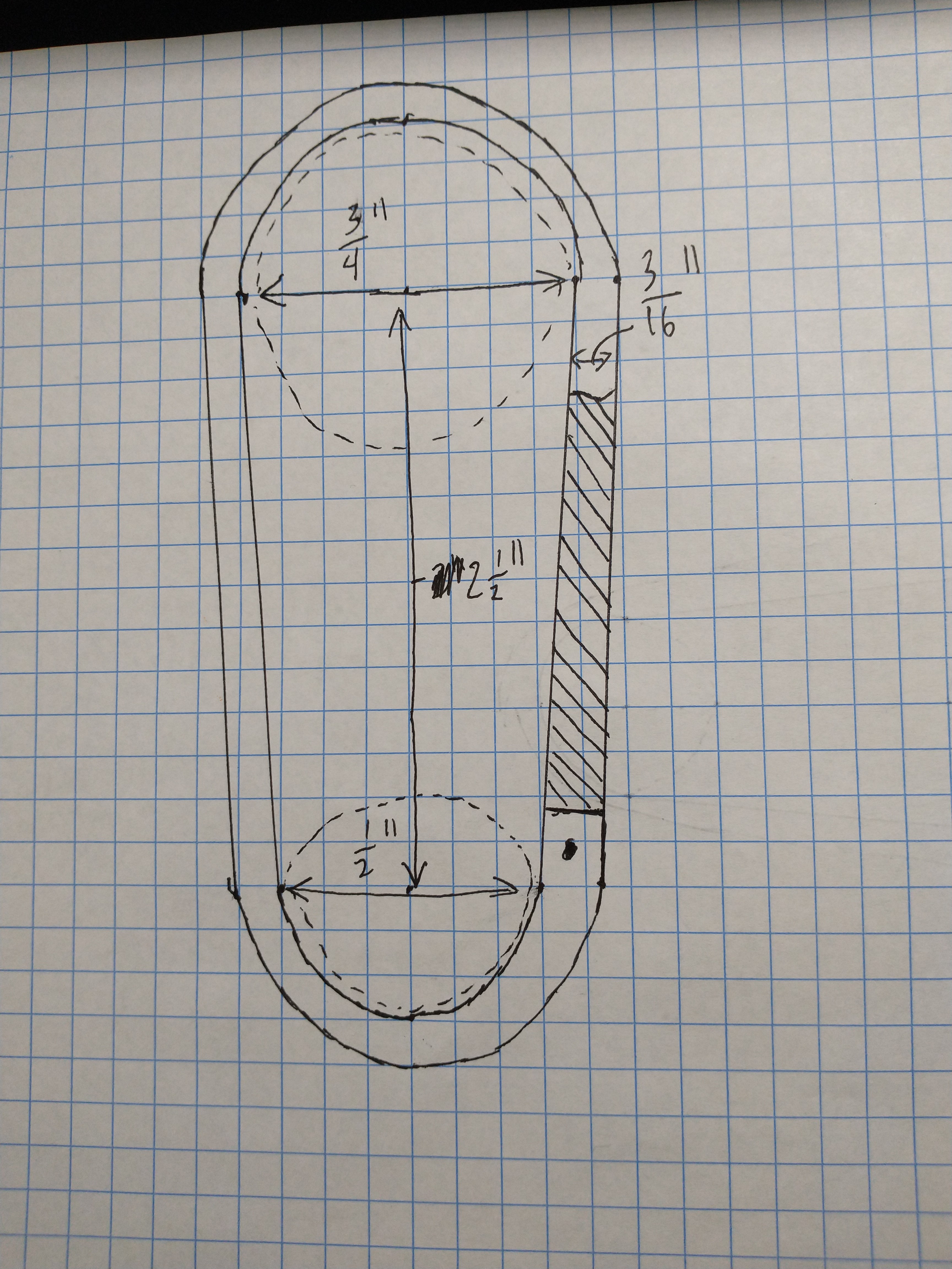
First, I placed a center line, with two circles on either end. Then I added dimensions that seemed appropriate.

Next, I placed one free line on the left side of my carabiner (free meaning not snapped to anything) that’s long enough to overhang both of my construction circles. Then, I made the free line tangent to both circles so they would connect at the right spot.
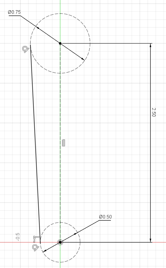
After that, I used the “Trim” tool in the Modify section of the sketch toolbar (scissor icon in the middle). The trim tool is quite useful, it allows you to drag across unwanted parts of a sketch. It also automatically deletes the part from where you dragged to the nearest node.
So here, the trim tool automatically cut down the hanging end of the line so it now terminates at the point where it contacts the construction circles.
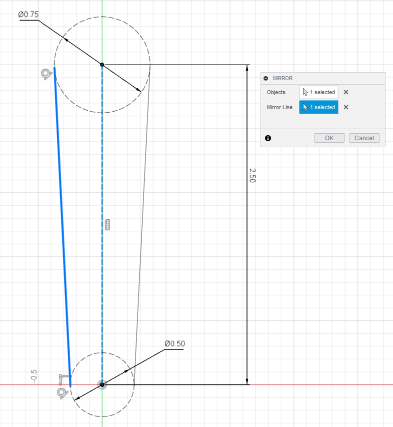
After that, I used the mirror tool to mirror the cut line across to the other side of the carabiner. The mirror tool (found in the Create section of the toolbar) allows you to mirror any objects over a mirror line. Symmetry is your friend, and you should use it whenever possible so you don’t need to go through and do any more work than you need to. The mirror tool is also time efficient and can be used for solid bodies as well.
After confirming, you will also see new constraint symbols show up on your sketch. If you do not know what a constraint is, click on the symbol and look for the text in the lower right corner of the screen. This can be useful for checking what exactly the symbol means, and when you click on one constraint symbol the others in the set of constraints will also become bold.
You can also click on any other part of your sketch (Point, line, circle), and it will tell you what it is, and it’s dimensions in the lower right.
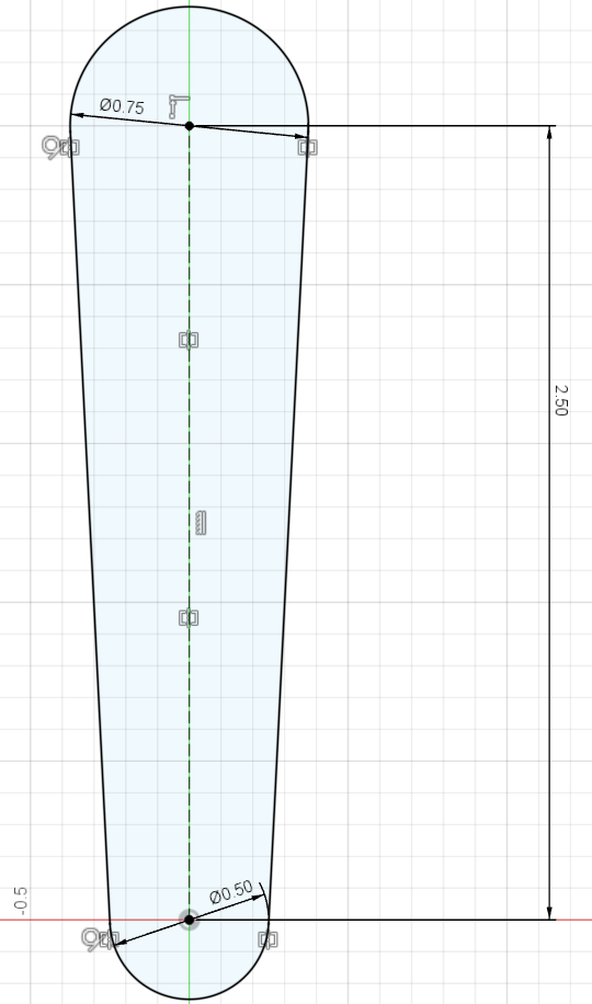
Now, I used the trim tool again to cut out the internal radii from the construction circles to create an arc, then make those arc’s back into a solid state by selecting them and pressing x.
You will now notice that the interior of the sketch has changed color, this means that the external sketch area is now officially a closed loop. Meaning that the interior is fully closed in, and we can now use Solid tools to create a three-dimensional object with said sketch.
Now that we have our final outline, we can use another handy tool to save us some time. To the left of the Trim tool is the Offset tool, letting us automatically create the same sketch as we just did but larger/smaller.
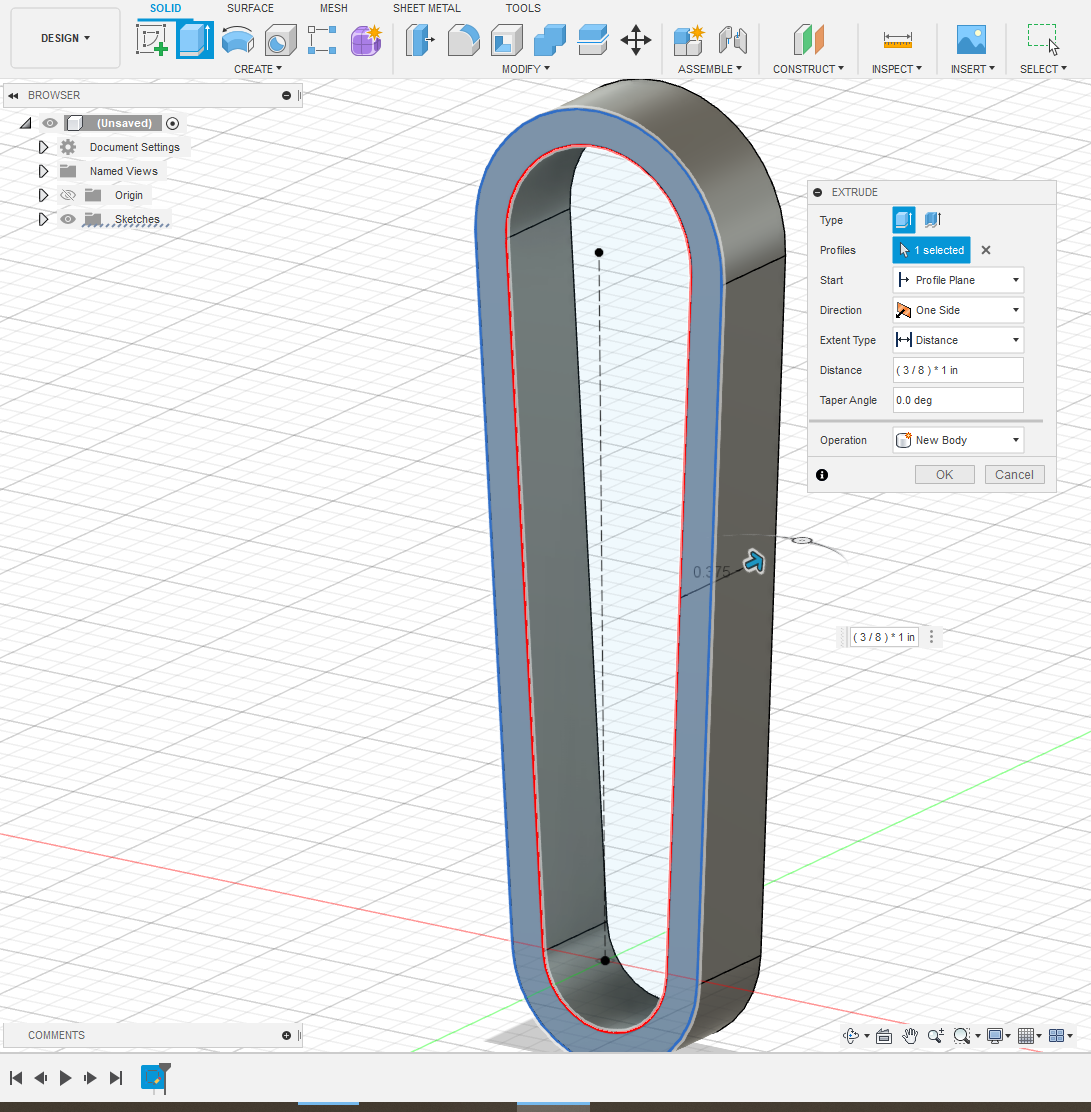
Finally, we can create this sketch into a three-dimensional part. Selecting the “Solid” Tab, then select the extrude button (left of the sketch button). Then clicking on the outer profile, we can extrude this sketch outwards.
Another handy tip for entering dimensions is that Fusion can automatically do math for you. Here, I just entered in 3/8 as a fraction and it will automatically change the dimension to 0.375. But you can also enter equations like (3/8)+(0.677*0.25) and (correctly formatted) it will do the math for you as well as save your equation so you can go back and change it without doing the math again. A place you should always use this is making a dimension larger/smaller for a specific tolerance. You can type in ((3/16)+0.03), and go back to change the added 0.03 without needing to remember what the original dimension was.
Now you should have some form of a solid body, and now you should see that inside the Bodies tab in the upper left.
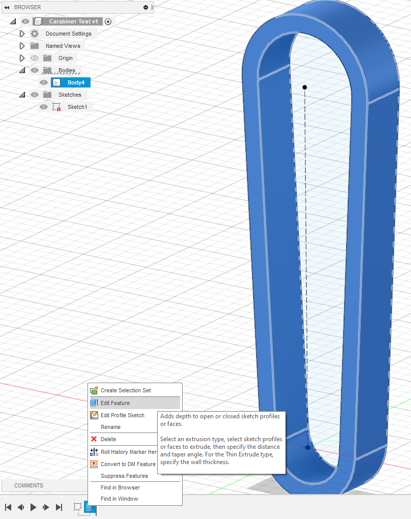
You will also see the extrude and a sketch symbol in the lower left corner of the window, along with something that looks like a video. This bar is the timeline, and one of the most useful tools in Fusion 360, the timeline records the sketches, extrusions, and other operations you make in your model. Clicking on the symbols will highlight them in the view window and in the document tree (upper left drop down menus), you can also double click (or right-click) on a specific symbol to edit that feature.
3D Printing
3D printing and specifically FDM is a form of additive manufacturing that can turn part files into finished parts using a variety of materials. FDM stands for Fused Deposition Modeling, creating parts by putting down material layer by layer until a 3D part is formed. With each layer being a cross-section of the chosen part file.

As a whole, you can 3D print out of materials from sugar to Kevlar, but we will be focusing on PLA and ABS. The two very common materials to print with.
PLA is a thermoplastic polymer usually made from corn starch. PLA’s advantages are its low cost, ease of printability and good strength.
ABS is another low-cost thermoplastic widely used in 3D printing along with injection molding. With better impact resistance and wear resistance than PLA. With the main disadvantage of being harder to print due to higher temperatures and increased warpage.
One of the most useful ways to gain a better understanding of different materials is by looking at the stress-strain curve. Showing the relationship between stress (σ), representing the amount of force the material is under per cross sectional area, measured in lb/in^2 or N/m^2. And axial strain ε, representing how much the material has changed in shape under a certain stress, measured in change in length (ΔL) / original length.
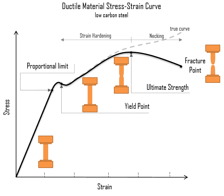
Figure X, Stress-Strain graph for low carbon steel
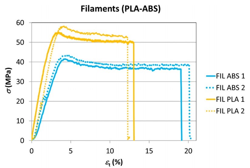
Figure _; ABS vs PLA Stress-Strain Graph
From these two graphs, what can we tell about these materials? The region from the start to the first peak is called the elastic region. We can see that comparing PLA’s graph to ABS, PLA has a steeper slope before the yield point. The slope of this line is the Young’s modulus E, representing the relation between tensile stress σ, and axial strain ε (E = σ/ε). So, looking back to the graphs of PLA and ABS, we can see that PLA is stiffer, and has a higher yield strength.
But this is not the whole story, since with this graph we can also measure the energy absorbed by the material, known as toughness. We find this by calculating the area under the curve created by the stress/strain graph. Comparing PLA to ABS, we can see that although PLA has a higher yield strength, the ABS graph has a greater volume under the curve, meaning ABS has better toughness and can absorb more energy before failing.
While the stress vs strain graph is a great tool, the main problem with comparing material properties from PLA vs ABS (in our case) is the manufacturing method. FDM 3D printing does not create a solid block of the printer material like injection molding would. One of the main variables is the printer setting applied for the 3-D printed part. A slicer program takes a 3D part in an STL format and cuts it up into multiple layers depending on your printer settings. Then generates a set of commands in gcode that tell the 3D printer how exactly to create the part.
FDM builds 3D parts from the bottom up (+z) so each ‘slice’ is in the XY plane with a set layer height. Because of this, printed parts will have a lower tensile strength along the Z axis compared to the X\&Y axes.
To get a better visualization of the slicing process, with the solid outline of your carabiner, click on the files dropdown in Fusion, select export, and export your part as an STL file. STL’s are the file type of choice for exporting 3D models since this file type takes your 3D model and breaks it up into a multitude of triangles. Allowing for easy scaling and processing inside a slicer.
Cura Setup: After downloading, open Cura. The setup does ask you to enter what 3D printer you are using the slicer for. Any of them should work, I chose a Prusa i3. Drag and drop your STL file onto the build platform. To orient the part flat on the build plate, select the part and press R. In the menu that pops up, click the right most button to align a face onto the build plate. Select one of the side faces and your part should now be laying down flat.
There are lots of specific print settings, but for now press slice with
the default print settings and go into the preview window (top center in
Cura). You will see two sliders, one on the bottom and one on the left.
The slider on the bottom controls the print linearly in time for a
specific layer. The slider on the right controls what layer is being
shown. For looking around the window, middle click to scan around,
scroll up/down controls zoom, and holding space then left clicking lets
you orbit.
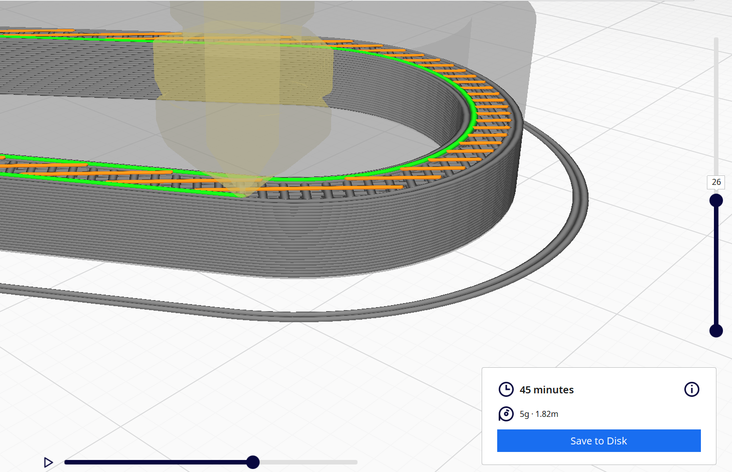
Zooming in and pressing play, you can watch how the printer will go about printing each layer, and how large each layer will be as the print progresses. You can also see how different layers have different colors, each color denotes a different type of line (clicking on the Line Type will show what each layer means). The major components are Walls, Infill, and Top/Bottom layers.
Walls generate as the perimeter for any part in a slicer. Adding wall count increases how thick they are before the infill is generated.
Top/Bottom layers generate on the top and bottom of parts. You can control how many layers of each generate along with how thick they are.
Infill is what fills up all the internal space of a part not taken up by walls or top/bottom layers. In a slicer, you can control what % of infill will be generated, along with what infill pattern will be generated. Different infill patterns have different strengths and weaknesses depending on their geometry.
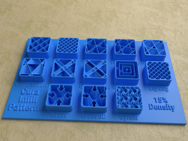
From Thingiverse
Introduction to Stress
Now that the easy part of designing a carabiner is done, we need to make
the complicated part, the gate. But before we jump into that, lets apply
some of what we learned from the previous unit on the outline of your
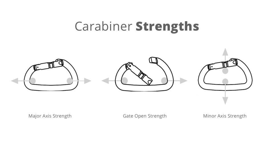
carabiner. While carabiners have three main force ratings (the main
axis, with the gate open, and in the transverse direction) we will only
be looking at its maximum strength along the main axis with the gate
closed.
Let’s review the fundamental types of loading, before we find out what the carabiner is experiencing.
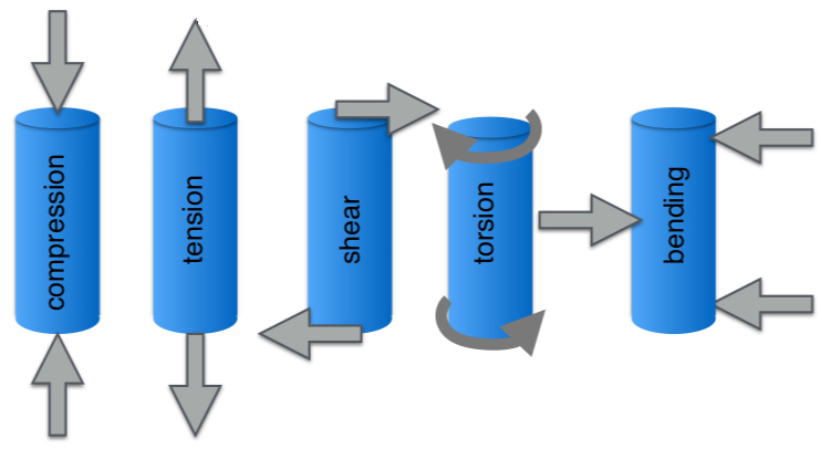
Figure _, _The five fundimental types of loading _
Looking at our carabiner, the loading on our carabiner is tension, and the bending effect brought by the two sides wanting to become perpendicular. While there will be some displacement from the carabiner being pulled thinner, we will be focusing on the tensile strength.
While the tensile strength of PLA is known, since we will be 3D printing calculating the exact material properties is not exact. As not only will your 3d print have different strengths along different axis (we will be going into that below), but your 3D print will not be entirely solid. Therefore, I will be making an assumption to save us from going in depth on modeling the exact part as it’s 3d printed. I found a _paper_ where they tested 3D printed PLA and found the ultimate tensile strength was 32.94 MPa (4777.5 PSI) with 80% infill. Which is about as solid as you’d want to go for 3D printed parts. We will be using these numbers to get a rough idea of how much force a carabiner can withstand without a gate.
Now we need the cross-section area of our carabiner, since tensile strength is measured in psi (pounds per square inch). One side of an example carabiner measures 0.2in * 0.2in = 0.04in^2 * 4777.5 psi = 191.1 lb. So, our theoretical maximum tensile strength for this carabiner is 191.1lb * 2 (both sides) = 382.2lb.
Designing the Gate
Now, let’s work on the gate of the carabiner, the main purpose of the gate is to allow a gap in the frame of the carabiner letting you attach whatever is needed. While also having a mechanism to automatically re-engage the gate once it has been opened (I will be referring to it as the sprint return, but it doesn’t need to be a spring). Since we know roughly how strong the frame itself is, the goal is to design a working gate that can hold at least that much force. While we will be 3D printing, let’s have a look at some common metal carabiner designs.

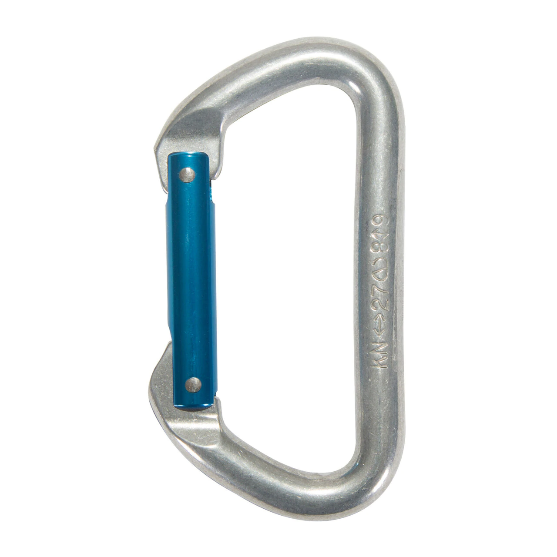
Hook Pin-Hook
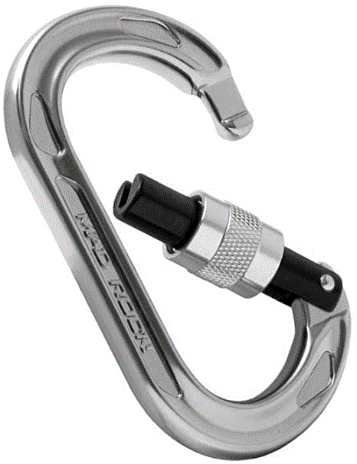
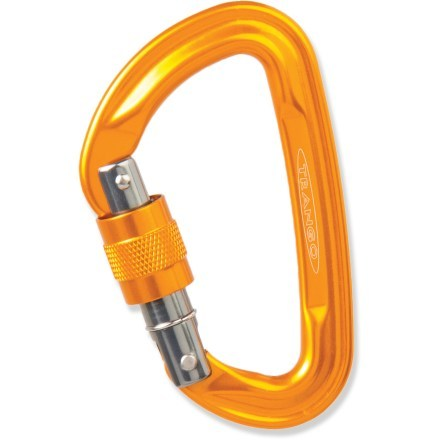
Screw-lock hook Screw-lock pin
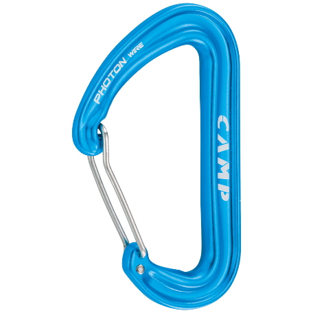
Wire Gate
Looking at these designs, let’s look at each part of the carabiner’s gate. They have a bottom pivot, a hook on the non-pivot side, some form of spring to keep the gate closed (inside the bottom pivot for most designs) and an optional gate lock.
On a side note, while looking at the pins on some random carabiners I had, I noticed that one was slightly more silver than the rest. A quick touch with a bench grinder confirmed that the pin was actually made of aluminum. Great example of why to NEVER use non-climbing rated carabiners for climbing, or any other tasks involving suspended loads.
Here, we will be dealing with shear stress (as noted above). Shear stress is any stress that is acting parallel or tangential to a surface. Let’s look at the most simplistic representation of shear, a single shear plane. The formula for average shear stress (denoted here as τ) in a plane is
τ = F / A
Where F is the resultant shear force acting on the pin from the plate. And A is the area of the cross section.
Plugging in the formula for the area of a circle since we are using circular pins, τ = F / (π*r^2). This formula is for normal shear stress, since we are applying a force to a pin the way it transmits that force onto the contact surface is called bearing stress. Bearing stress is the contact pressure between separate bodies, and in our case is between the plate and the pin.
While not exact, the force distribution from this bearing stress on the inside of a hole, and the resulting displacement will look something like this.
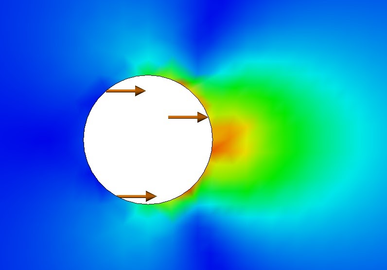
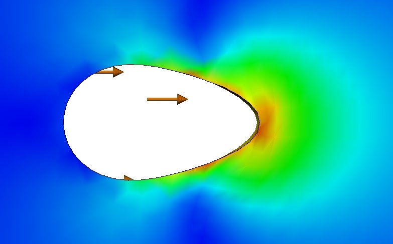
Un-deformed bearing load. Deformed Bearing Load.
Single Plane Shear
Before we go onto the carabiner pin, let’s look at the simplest example with a pin and a single shear plane. Where the force is spread out along one cross sectional area of the bolt.
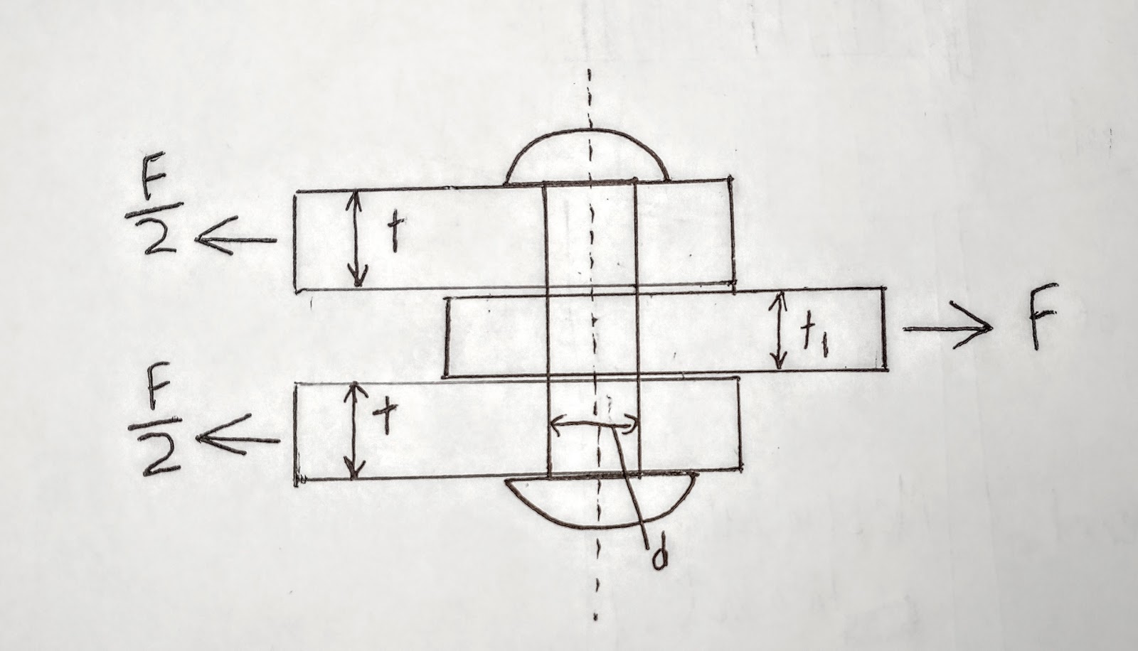
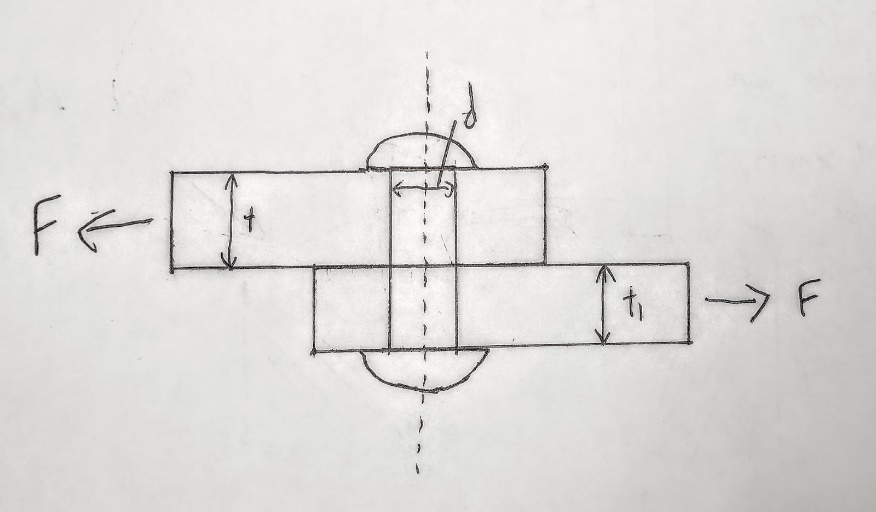
Double Shear
In a double shear scenario, there are 3 total plates creating two shear planes within the pin resisting the shear force. So (as labeled in the drawing) the average shear stress on each plane is equal to ½ of the total force. Going back to our formula but for double shear.
Going back to designing the gate, another design for the bottom pivot and spring is using the PLA itself to act as the gate and pivot without a separate part or pivots. This is usually done by making cutouts in the lower part of the gate, using the elasticity of the material to make a small spring section that is printed along with the frame in the same print.
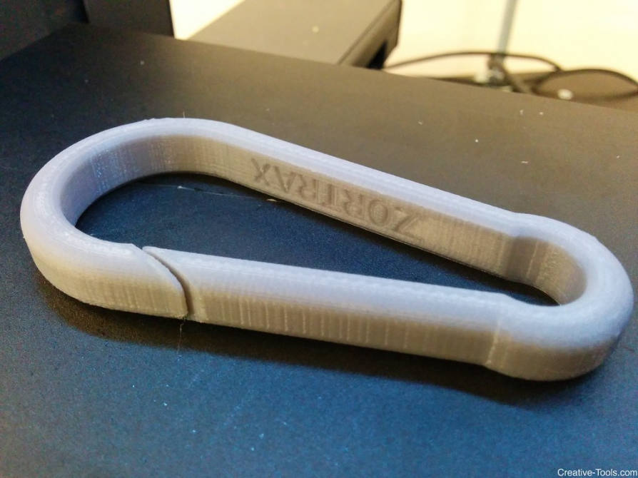
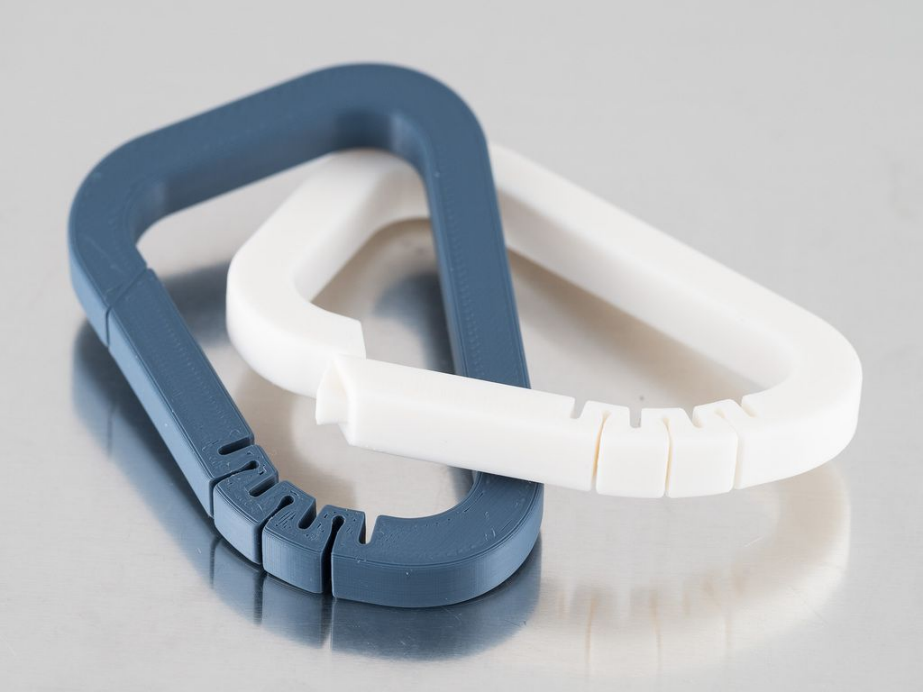
Looking at the second design, the ‘spring’ section has match head shaped cutouts, going part way through the width of the frame. The match head shape of the cutouts is notable, since that shape helps to prevent stress from concentrating in that area. Reducing the likelihood of it cracking under use.
To create a CAD design of the gate, there are two main paths. If you are going to make a single part where the carabiner is printed in one go (like the photo above), it would be easiest to keep everything in one part. But for my example carabiner, I will be making a separate gate to be assembled with a metal pin.
Creating assemblies is the next major part of CAD design after creating the parts themselves. Assemblies are where you take multiple parts, and assemble them together virtually. You can also analyze how your mechanism will move, check for interferences between parts, and run simulations.
Creating a CAD of the Gate
I will be breaking the CAD process down into a few major parts. Modeling of the gate itself, modeling the pivot pin, Adding gate components to the main Carabiner frame, then assembly of the gate and pivot pin.
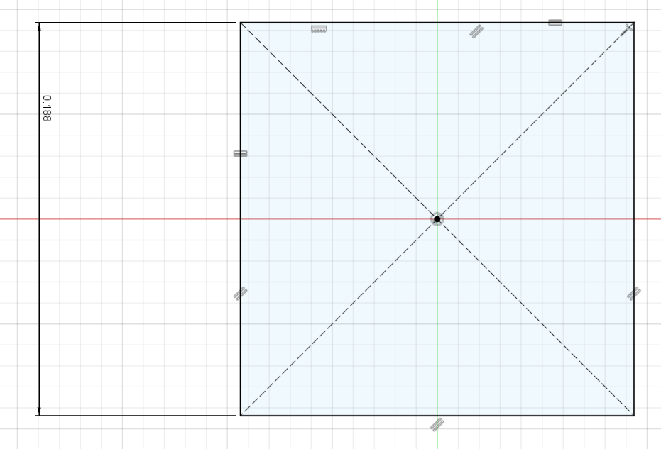
First, I made a sketch of the main body will look like based on my sketch.
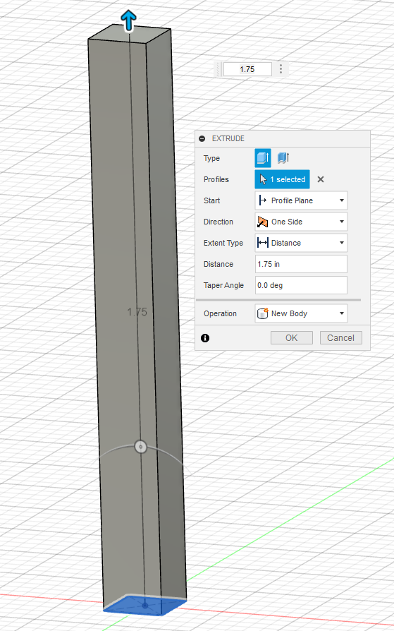
Then, I extruded that sketch out to my desired length. Since I started on the Top Plane, this extrusion is up along the Front plane, centered on the +Z Axis.
Then, I created another sketch on the surface of the body made in the last step. The arc is a 3-point arc with the two end points being horizontal to the sides of the first extrusion. Then the middle point of the arc is constrained to the origin of the sketch. Making the arc tangent with the side of the rectangle means the arc is now fully defined without needing to add any dimensions. Meaning the arc will now stay the same no matter how the width is changed.
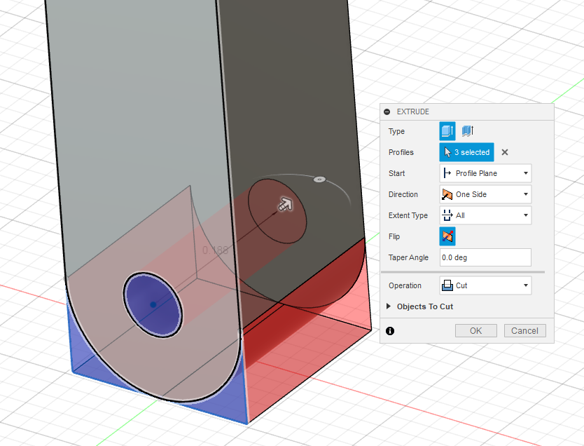
Since this sketch needs to be a cut we select extrude like normal, and change the operation to cut. Instead of setting a hard distance, I selected the Extent Type to ‘All’ meaning the cut will automatically extend to the farthest point of the solid body in front of the sketch profile. Now, if we need to change the width of the body down the line the cut will now automatically extend without needing to go in and change any values.
Next step is cutting out top and bottom of the gate to define where it will connect with the main body of the carabiner, starting with the bottom pivot.
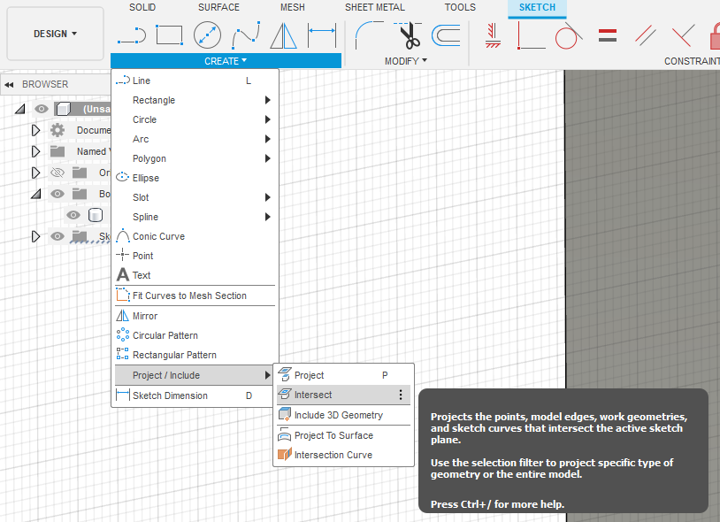
I start the sketch on the right side of the body of the gate (aligned with the right plane). For the sketch to create the cut outs for the pivot, you can’t select or snap onto the curved section, since it’s not in the sketch plane. Here, we use the ‘Intersect’ tool to convert sections of bodies and pull them into your current sketch plane. This tool is also quite useful, and does almost the same thing as the Project tool except specifically for non-bodies.
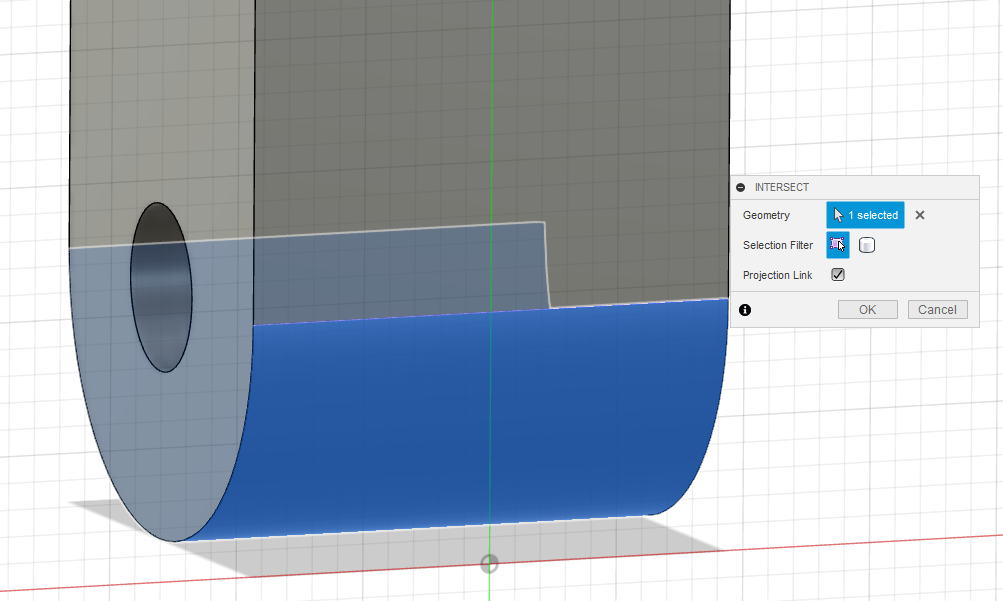
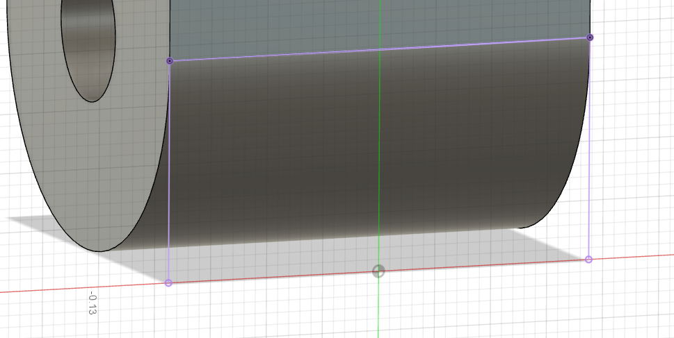
Select the intersect tool, then click on the curved portion of the gate and hit OK. You should now see a pink outline of the square profile extended onto the sketch plane.
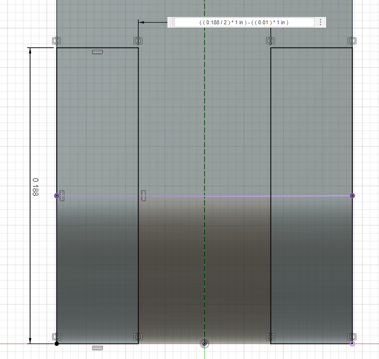
For this cut extrude, I first added a construction line down the center for mirroring. Then added a 2-point rectangle on the left side. I entered a height, then mirrored the rectangle and added a final dimension between the two rectangles. The cutout is finished by applying a cut extrude, through all.
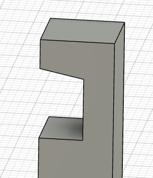
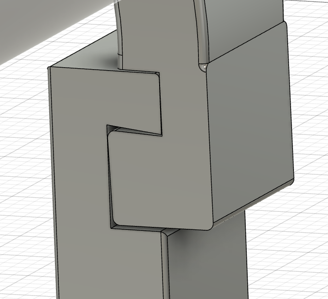
Next is the cut out for the top hook, I decided to go with a simple hook-and-pocket type design, with the pocket side being on the gate. The main reason the pocket is on the gate has to do with print orientation. Since the only real way the main body can be printed is on its side (like we did before), if the pocket was on the body, it would have support material inside. While the support material wouldn’t be too annoying to take out in this case, I decided to avoid the problem altogether since the gate can be oriented with the cut-out upwards without any major downsides.
First, we need this to line up with the hook part in the body of the carabiner, so I’m going to get a rough sketch of what the hook will look like. There are a multitude of ways you can go about designing an interface like this, and I will be showing a good starting point for design.
Sketching on the front plane, I started by just laying out a rough idea of what the middle should look like without adding any dimensions and just dragging the (blue) non defined lines until a point where they are roughly what seems right. Add in the dimensions that automatically show, then making it an extrude cut and boom, we have a rough hook.
Now, with the gate in an initial state, before we go too far let’s start assembling them to see what they look like together. I usually like to do this early in the design process before putting any finishing touches or getting too fancy with my models. An important quote that has stuck with me throughout my education in engineering is “Fail fast, and fail early”. To that end, making a mock assembly early can help catch errors as early as possible, so they can be fixed as easily as possible.
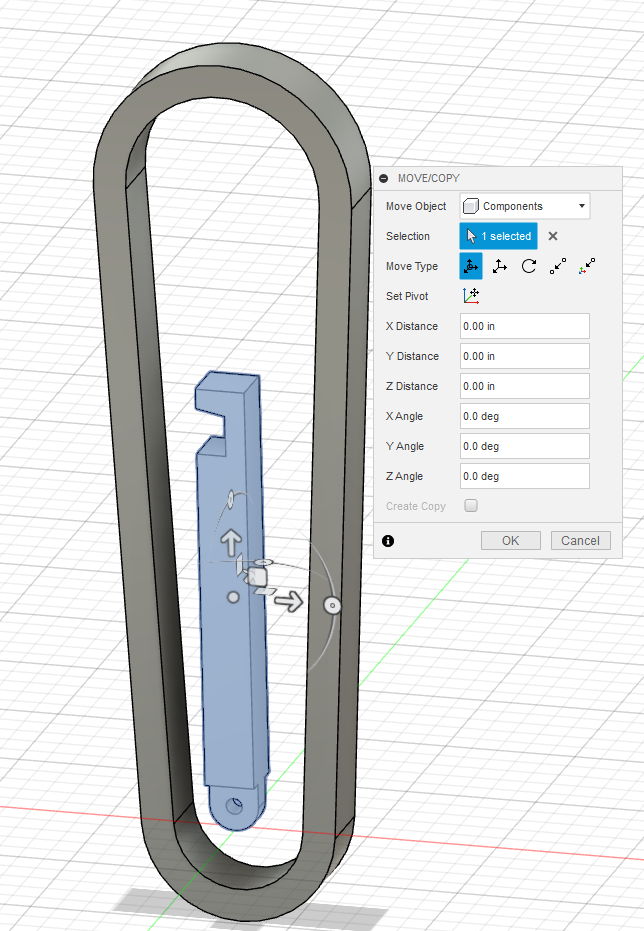
Opening the data panel, double click to open (or go back to) the main body of your carabiner, then simply click and drag the gate into the view window, your screen should look something like this. On the gate, you will see three arrows and 3 arcs, the arrows will move the part in X, Y and Z, and the arcs will rotate your part around the axes. Use these controls to roughly alight the gate to the carabiner, and hit OK.
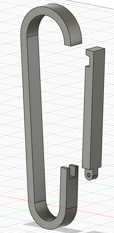
And look at that, not too terrible. Now is where you might realize some things you want to change, like for example the length and width is not quite what I want.
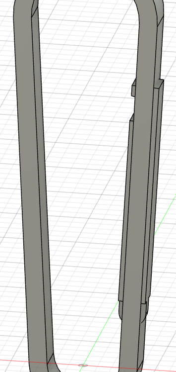
Next is the cut out on the body of the carabiner, leaving the gate as a rough overlay I roughly cut away all the material except the area for the bottom pivot. No need to be too exact since we will be going back once the gate is locked in place.
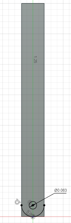
Next step is adding the pivot and clearance for the bottom pivot hole, I did this in a single sketch.
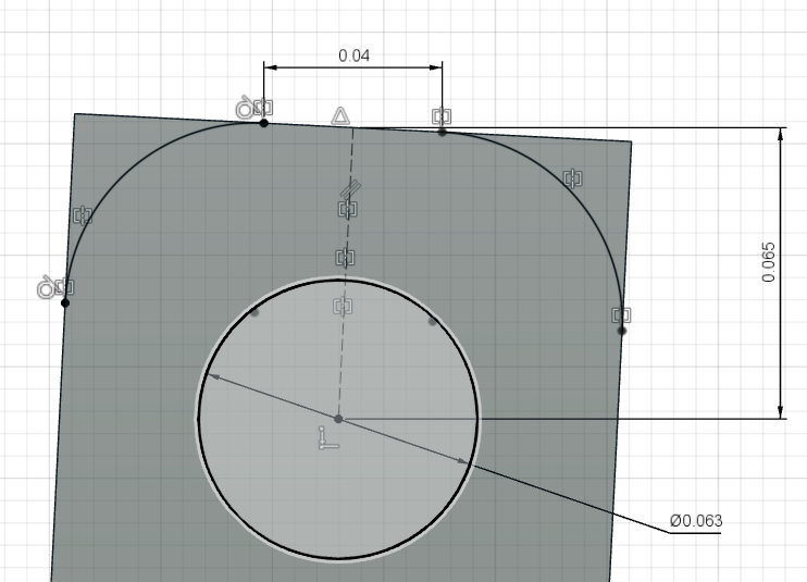
Another quick note you might notice that when adding dimensions even if the overall sketch is at an angle the dimension automatically measures along the major axis.
To change the dimension to being along the actual length of the line, after selecting said line put your cursor directly besides you line. It may take some wiggling back and forth but you should see the dimension switch to being aligned perpendicularly with the line.
With both pivots in, the last part that needs to go in before we can create a joint is the pin.
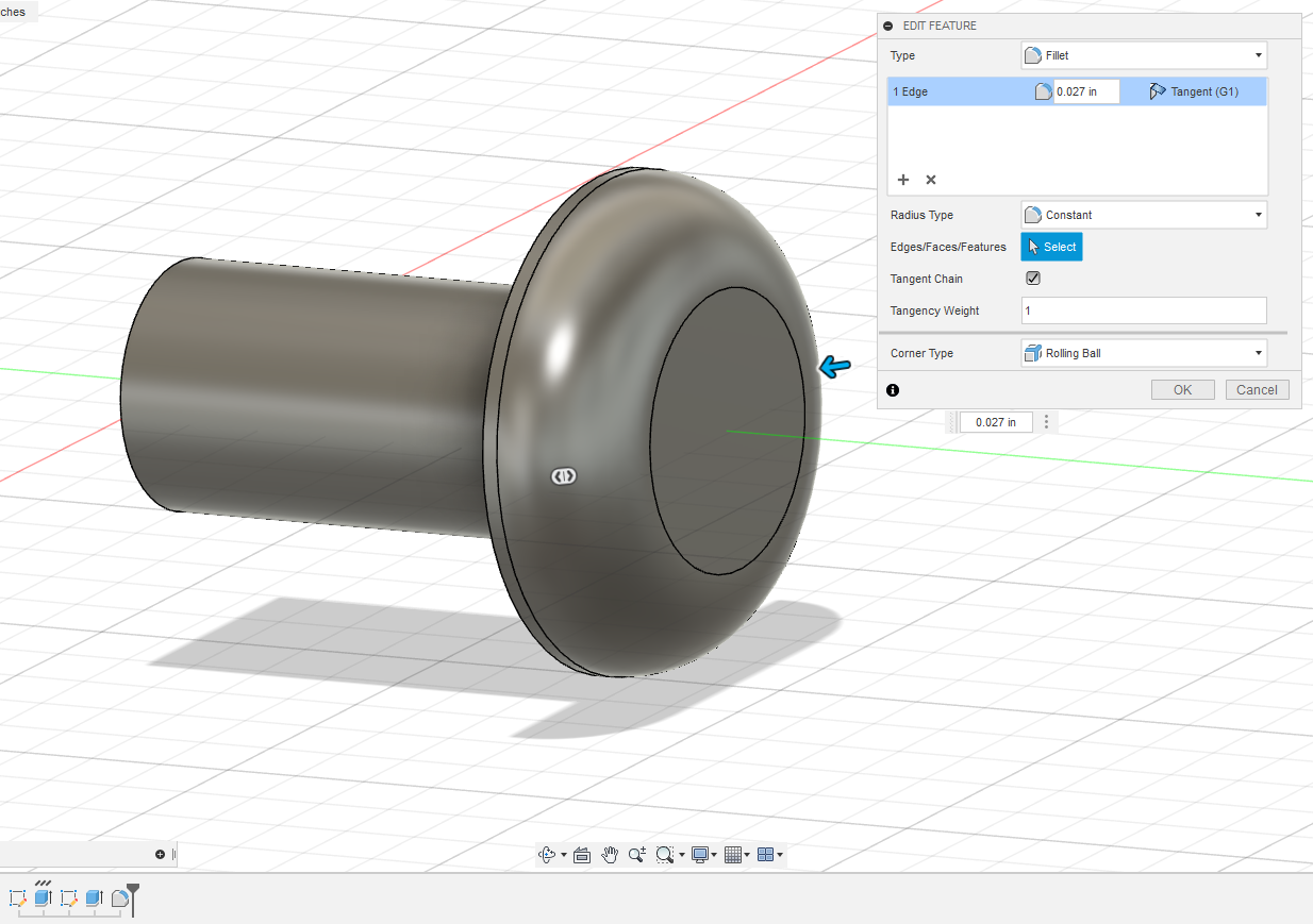
For parts like these, there are two main ways to go about designing them. First is creating the part section by section with individual sections. The middle of the pin, the head of the pin, and then a fillet to create the curved surface on the head of the pin.
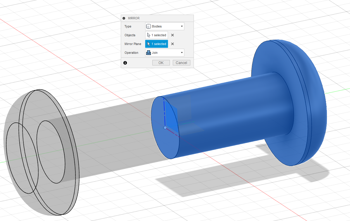
Then mirroring the body to create the other side of the pin.
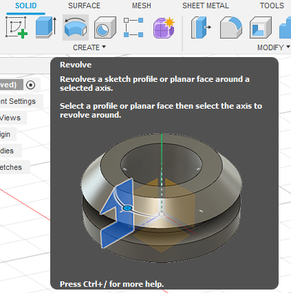
The other method is creating the pin with a Revolve Operation. For a Revolve extrude, instead of creating the pin with multiple separate sketches and extrusions, you create it all in one operation by sketching a 2D side profile of the pin, and revolving it around the centerline.
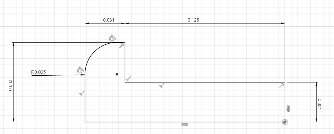
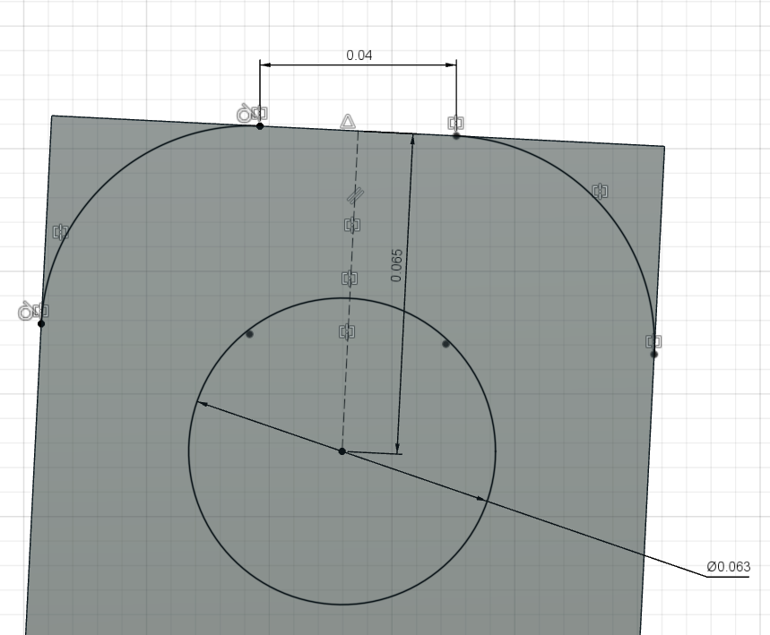
Step 1 would be making the simplest sketch of the profile, here we only need to do ½ of the cross section.
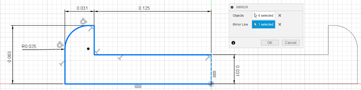
Mirror the sketch to create a closed chain.
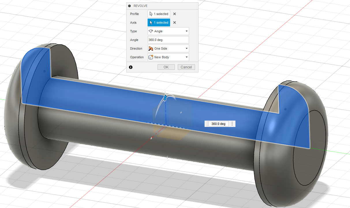
Then revolve the profile around the central axis.
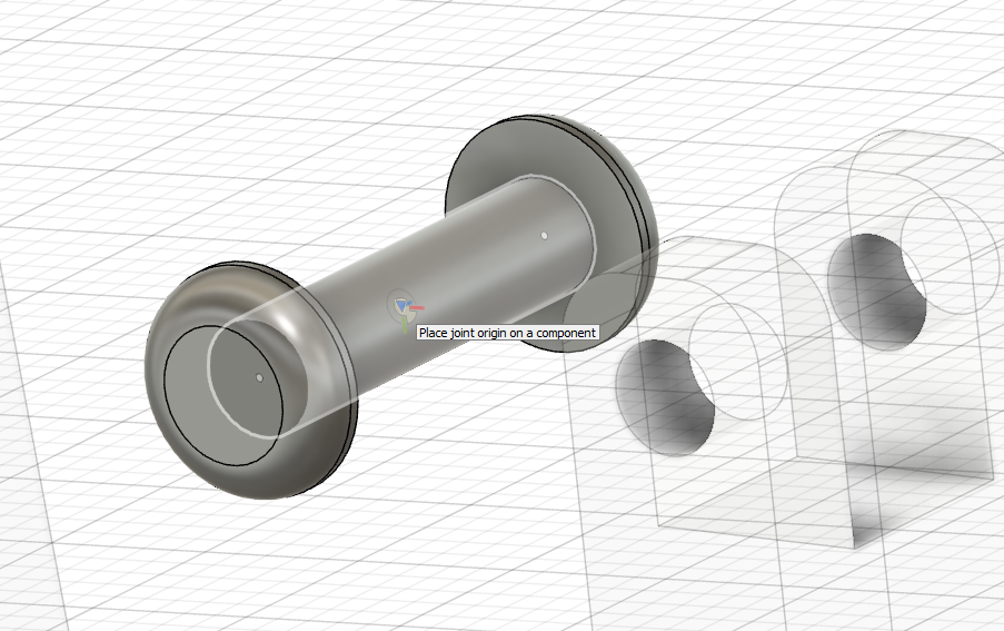
Now that we have out pin, we can start assembling the bottom pivot of the gate. As we’ve done before, drag and drop your part in and roughly position in close to where you want it in.

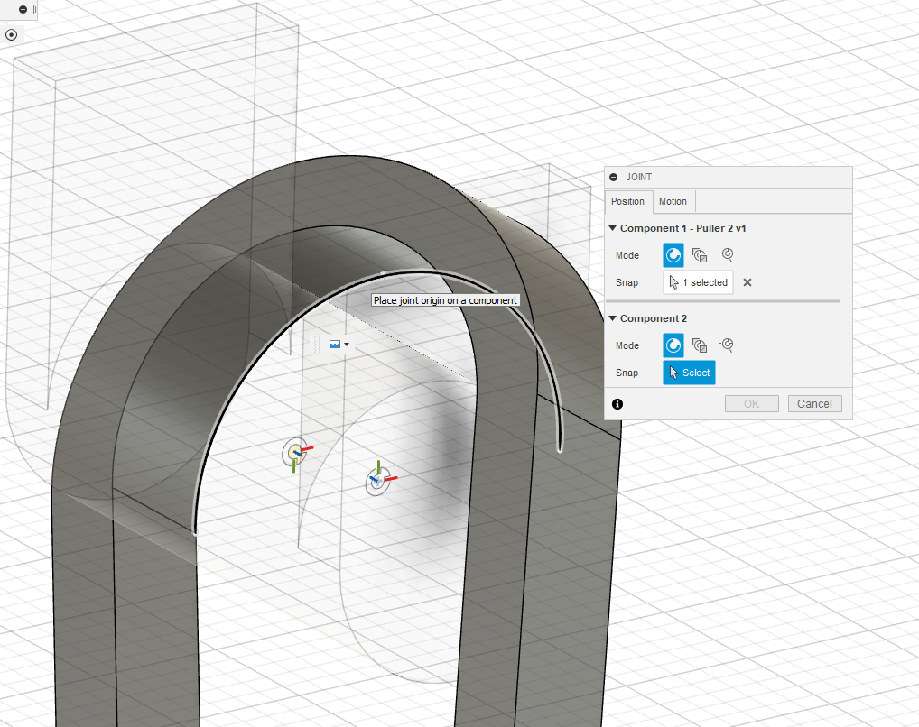
For assembling parts, we will be using the Joint tool (Hotkey J). The joint tool allows you to define how two bodies connect and interact with each other.
For each joint there are 7 joint types that define the motion in that joint. These are Rigid, Revolute, Slider, Cylindrical, Pin-Slot, Planar, and Ball. For the pin, I will first be using a rigid joint to join the pin to the body of the carabiner.
The Position tab is where you select where the joint will be located on a specific part. The three modes are simple, between two faces, and two edge intersection.
Simple: Creates a Joint Origin on a face, edge or point to align components.
**Between Two Faces: **Creates a Joint Origin to center a component between two faces.
Two Edge Intersection: Creates a Joint Origin to align components to the apparent intersection of two edges.
In general, for creating joints you always want to apply the constraints to the part that is the least likely to change down the line. So, for the pin I chose the simple mode, and placed the part origin on the origin of the pin.
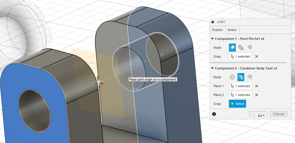
For Component 2 (the frame), I chose the in-between two faces option since the center of the pin is centered between the two outer faces of the frame. Here, Plane 1 and 2 are the main side faces of the body, and ‘Snap’ is what defines where the origin on component 1 will be located between the two planes defined. I chose the Snap point to be the center of the line between the two holes of the pivot.
The origin symbol (the circle with the three colored lines for each axis) should snap to the midpoint when you put your cursor over the center of the hole (see above).
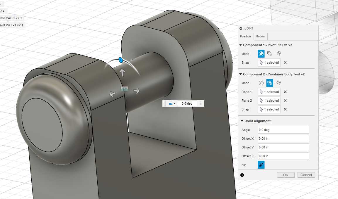
Now you will see the component move into place, and where you can add an offset or angle of your part if desired. You can also change this by dragging any of the arrows or the angle slider on the component.
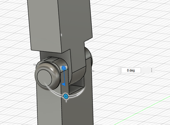
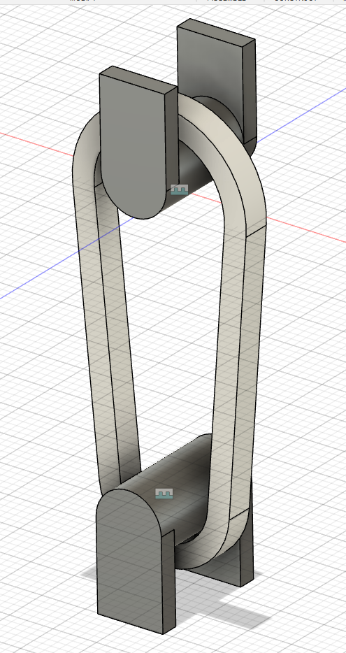
To join the bottom pivot of the gate to the pin, the process is similar except that we want the gate to be able to move. Therefore, we want the ‘Revolute’ joint, after adding the position (same as before) Fusion will animate the gate spinning around the pivot. Left clicking and holding lets you freely move around constrained parts, allowing you to see how it would move in real life. You can also double click on the Revolute Join symbol (the flag) to enter a specific angle.
With the gate in place, it is now much easier to create the top hook by positioning the hook to the needed position and sketching around it.
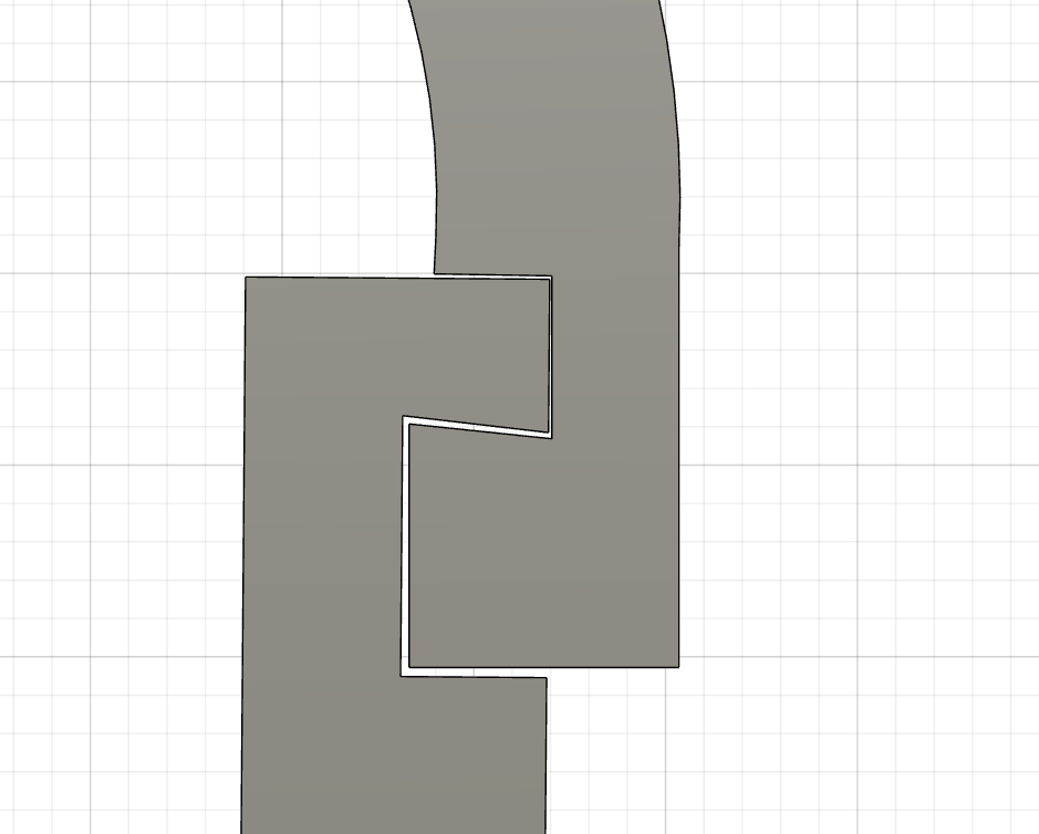
After creating the feature, now you need to check for interferences with the rest of the carabiner. Here it is simple to tell it will interfere without moving the gate. But stay with me, for more complicated geometry it’s not as easy to see interferences. Moving the part to where you think the interference is, and select the interference tool from the Inspect tab.
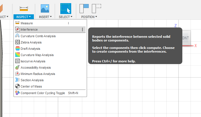
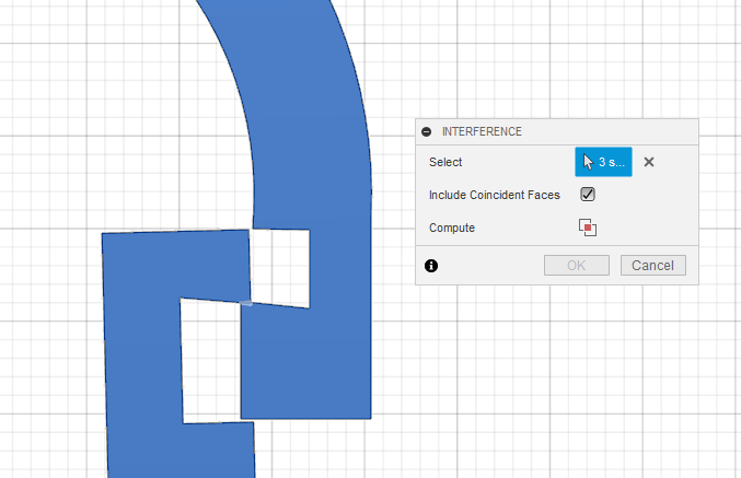
Selecting the bodies involved, and including coincident faces to check they are actually coincident, we can compute the interference.
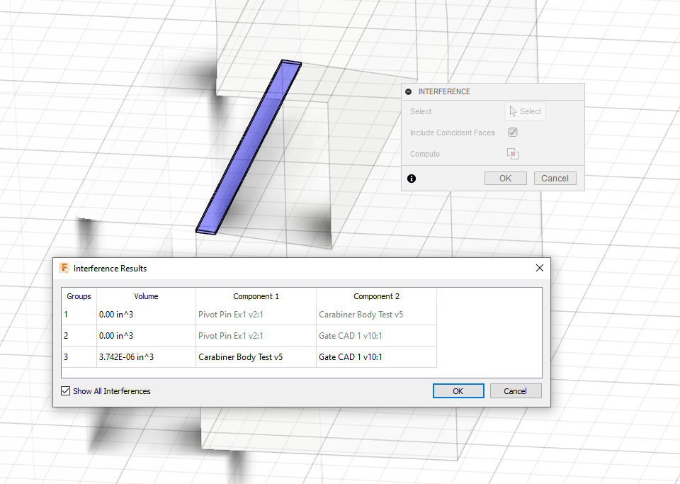
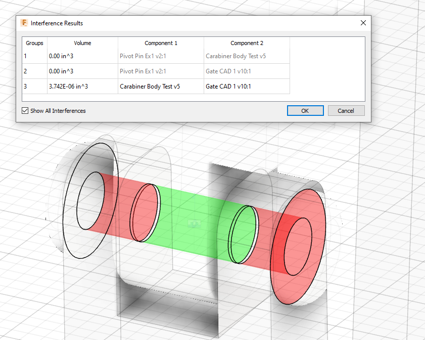
The results box will list the interference(s) and their volume, along with what components are involved. The interference can also be seen colored on the model.
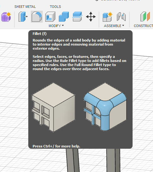
Now, with the major parts finished it is time to add in fillets. A Fillet is the rounding of an exterior or interior corner of a part.
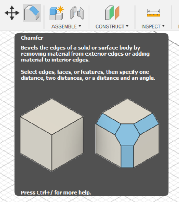
With fillets there are also chamfers, they serve the same function as fillets but they are angled instead of rounded.
Fillets serve to reduce stress concentrations that are almost always found at the corners of a part. Adding a fillet into a corner spreads the stress from where it would be concentrated right at the corner to being spread over the fillet.
Lowering the overall stress on the corner.
Before creating fillets of chamfers for 3D printed parts, it is important to keep the print orientation of your part in mind since the strength of the fillet can vary.
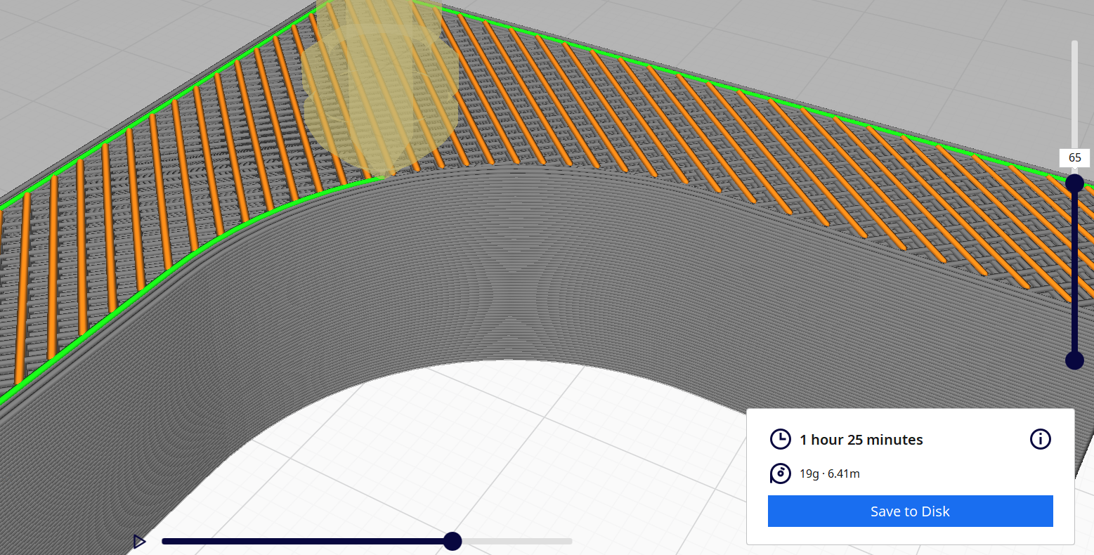
When the fillet is horizontally aligned with the print bed, the fillet itself will be printed as a single curve, the print head is able to track the path of the fillet with one continuous line.
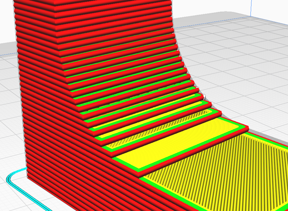
But when the fillet is oriented to be vertically aligned to the bed, when sliced the fillet is jagged (slightly exaggerated here with a 1mm layer height), and compared to being aligned horizontally will not be as strong (or look as nice).
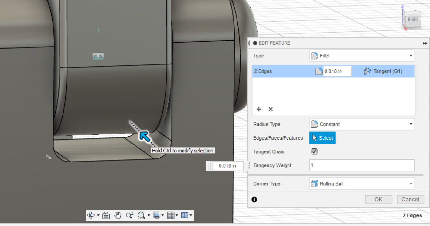
In the fillet tool, after selecting the edges you want to fillet and drag the arrow until you the fillet is the right size. For 3D printing I usually don’t round to a fraction or a whole number like I would if the part was going to be machined or made into a drawing for fabrication.
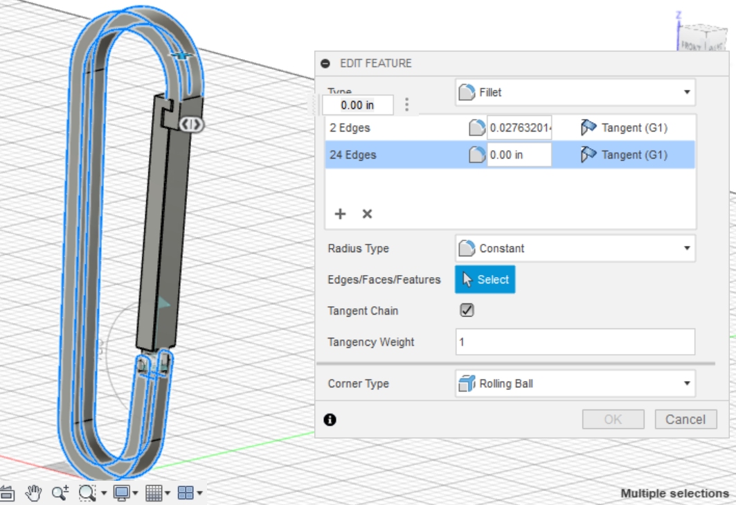
Instead of clicking OK and creating another fillet feature for the next set you want to add, clicking on the + will add another selection set allowing you to keep all your fillets organized. This is also why I save adding fillet features until the end, since you can keep all the fillets together in one feature.
The Tangent Chain option is also helpful since it allows you to select entire chains instead of selecting all the edges individually.
By now, your model should be in a good shape. There are also other features you can add like a specific appearance, or adding any branding like your name or a logo to your model, but I will not be going into that in detail.
Introduction to FEA
FEA Stands for Finite Element Analysis, which is an analytical method for solving complicated analysis in many fields of study from structural analysis (what we will be doing) to fluid flow, heat transfer, vibrations, etc. The basic idea of FEA is to break up a model into small, manageable sections that can be more easily solved by a computer. Which is great for us! Since trying to hand calculate forces on structural parts can be quite tedious.
While the computer will handle all the math for us, creating a simulation that will generate useful information takes proper preparation and setup. While FEA software built into programs like Fusion 360 is great since it is easy to use, but a problem is the concept of “garbage in, garbage out”. The idea that if you put in flawed data into a logical processor (the FEA program, in our case) the output will also be flawed.
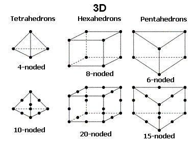
The basis if FEA comes down to the elements themselves, and the nodes that connect them. Depending on the exact geometry, the software will calculate a new representation of your part made of elements and nodes. _Above_, we can observe how some of the simpler elements are constructed, and the different nodes they can be made of.
This first FEA example will only be on the frame of the carabiner. I will be going over the full carabiner FEA afterwards since that follows almost the same process. But if this is your first time using FEA or CAD software like fusion, there is a change the specific geometry of your gate may give you errors in your simulation that may not be easily solvable.
I chose to go back to the simplest version of my carabiner, where I had only drawn the outline and extruded it.

Scrolling through with the controls on the left (or the slider), go back to the initial full extrusion of your carabiner. You can now use this for your initial simulation without creating a new part file.
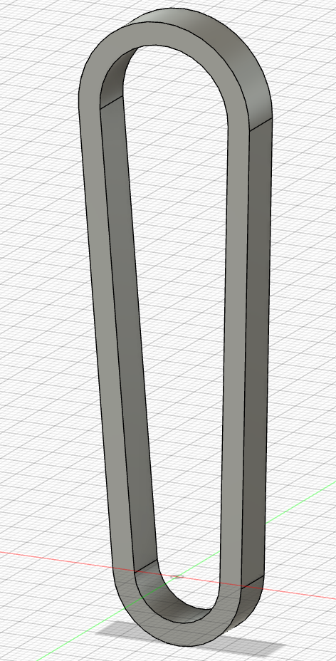
This is a good example of how the timeline is helpful, yours should look something like this now.
In Fusion, go to the design tab in the upper right and select simulation near the bottom. When making a new study, Fusion has several different simulation suites available.
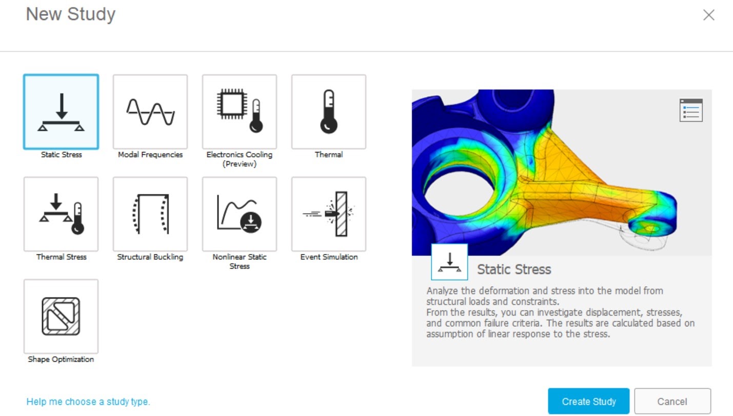
Feel free to go through and read the description for each suite, but the main study’s we will be considering are static stress, Nonlinear Static stress, and event simulation.
Even Simulation studies are meant to find out how your model responds to different factors like motion, impacts, and loads.
Nonlinear Static Stress studies are meant to determine the static stresses and deformation throughout a model caused by the structural loads and boundary conditions while considering nonlinear material properties and large deformations.
Static Stress **is the most basic FEA study. **Meant to analyze the deformation and stress on a model from structural loads and constraints while only calculating results assuming linear response from stress.
One of the main advantages of Nonlinear studies is it give a more accurate representation of real-world scenarios. Since many materials are nonlinear (like elastic plastics), there are also nonlinear geometry’s like for large deformations, and nonlinear kinematic constraints.
While both the Event Simulation, and Nonlinear Static Stress could be used in our application to find the resulting forces on the carabiner, we will be using Static Stress because of its simplicity, and ease of setup.
Now that we know we will be using, we will need to model our “rope” for our simulation. Looking at our model, you might thing we can apply a force going up on the top curve, and constrain the bottom of the carabiner to be stationary. But simply applying constraints to the whole inner surface of the carabiner will not accurately represent what is happening when force is applied from a rope.
To add this to our model, we will need to model two “ropes” and add them to our assembly to apply the right conditions to our carabiner.
My model rope was roughly 10cm in diameter and 1” long, with two square tabs on the end. The width and addition of the square tabs was arbitrary, but the diameter was what seemed to be a common size for rope.
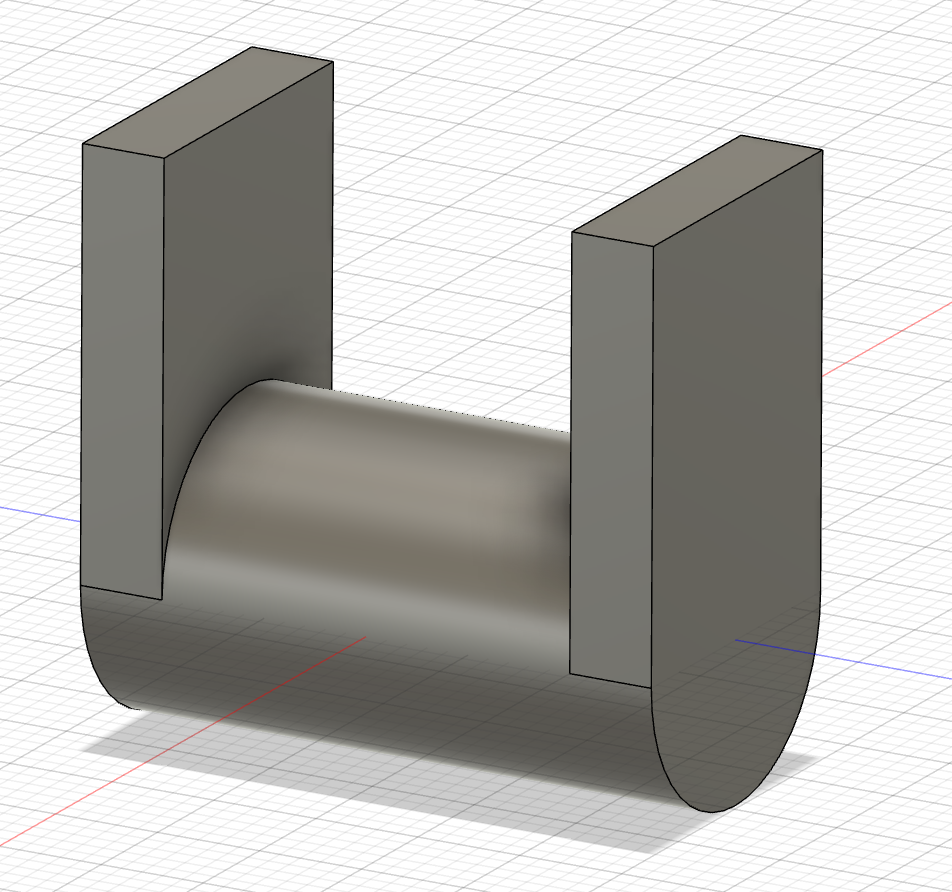
When applying the material for the rope, while we can create a custom material that is rigid as I cover in the next section, I will be making mine the in-built “steel” in Fusion’s material library since it will be rigid for our use. You can also see that I modeled this part so the origin is right in the middle of the part, taking the effort to place the origin in a sensible spot will now come in handy.
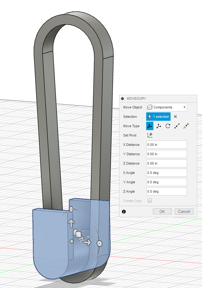
Dragging in the model and boom, it’s already basically in the correct place, no fiddling needed.
After dragging in two “ropes” (or the puller as I named it) roughly align them with the Move/Copy tool until they are roughly in the correct place. Now we need to apply joints to keep them in place and not be accidentally moved. I applied a rigid joint to both the top and bottom pullers, and moved them until they were as tangent as possible to the inside of the top curve.
Now we need to make the physical material of the carabiner PLA, but we run into a problem. Fusion 360 lacks PLA in their default materials library, and the additive material library. But going beyond that, we want our study to specifically apply to 3d printed parts. And as we went over earlier in the Introduction to 3d Printing unit, each print will vary depending on print settings and orientation. While in the future there will probably be some way to slice a part and do FEA on the virtual print file, for now we will account for this discrepancy by looking at available research.
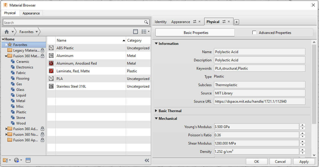
MIT has a comprehensive paper on PLA (_https://dspace.mit.edu/handle/1721.1/112940_). All the required mechanical values can be found in table 1. Don’t forget to check your units when adding them in (1 MPa = 1 N/mm^2 = 1 kg/m*s^2).
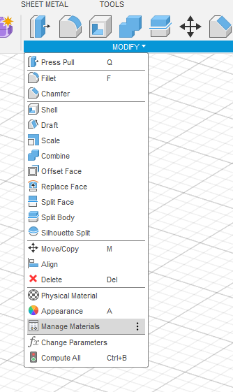
In the “SOLID” tab, click on “MODIFY” and open “Manage Materials” near the bottom of the drop down.
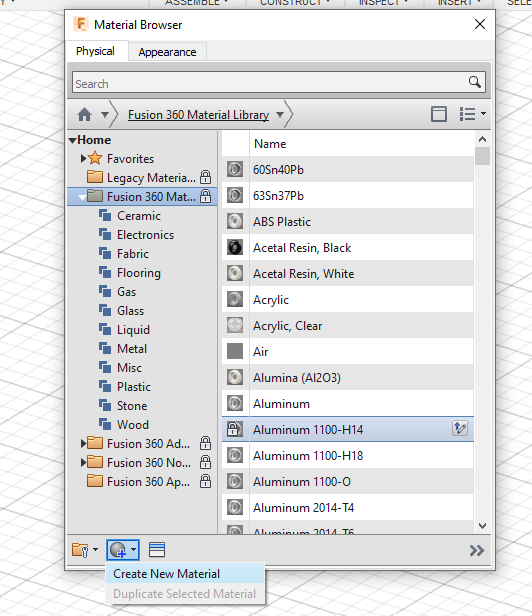
In the Material Browser, click on the circle icon with a + mark on the lower left corner of the window, then click “Create New Material”.
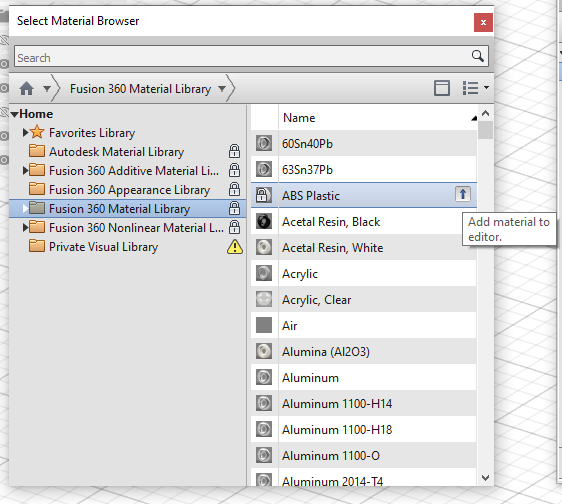
In the window go into the ‘Fusion 360 Material Library’, click on plastic and find ‘ABS Plastic’, then add the material to the editor.
Close the window, and you will now see the ‘Identity” “Appearance’ and “Physical’ tabs on the left of the window. Fill in the required values in the physical tab, and fill out the Appearance and Identity tabs. Don’t forget to list the source URL so you will know where these values came from if you go back in the future. You can also edit the materials appearance and other properties here. The material should now show up in your favorite tab, so we can apply it and move on with our simulation.
With the materials applied, we need to move onto adding constraints to our study. Fusion gives us several tabs for adding information into our simulation before we can run it. Opening Load Case1, consisting of loads and Constraints.
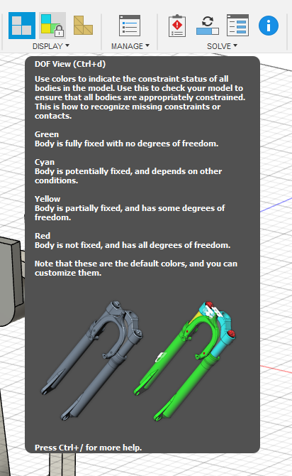
First, we need to constrain our model, in the Display tab, click on the DOF View button in the middle. This is the DOF or Degree Of Freedom view for our study. You will see that all of our bodies in the study are currently free.
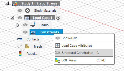
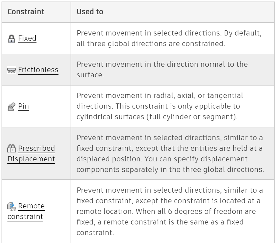
For our study, the lower puller will not be moving. Click on ‘Constraints’ in the tool bar and add a structural constraint (Also in the modeling tree, or hotkey C). There are 5 constraints to choose from, but for this study we only need Fixed, and Frictionless constraints.
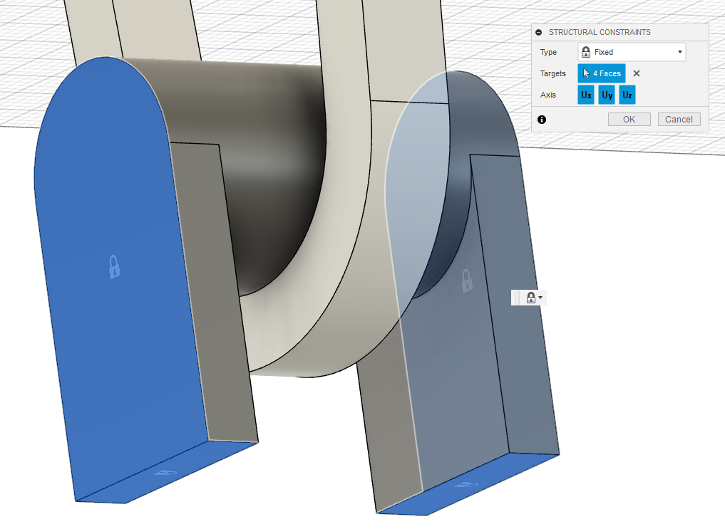
Select the bottom faces of the carabiner puller, it will now be fully fixed in place.
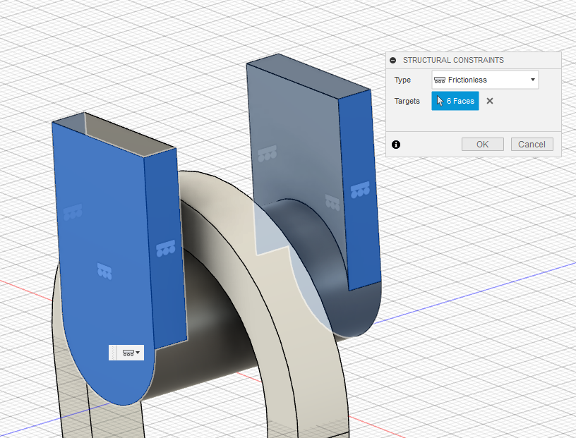
Next, we need to constrain the upper puller. Since this part will be sliding upwards, simulating a rope pulling the top of the carabiner, we need to use the ‘Frictionless’ constraint. Select only the outer x and y faces of the puller and click ok. These constraints mean that the puller can now only move up and down, in a virtual “Channel” crated by the outer faces of the puller. There should also be a frictionless constraint applied to the two main faces of the carabiner to prevent side to side movement.
With our structural constraints in place, and before we apply our loads, we need to create a contact set. A contact set is basically a way to identify a relation between two parts and how they interact with each other. Right click on ‘Contacts’ and select ‘Manual Contacts’. (There is also an automatic contacts tool, but since we only have two doing it manually is fine).
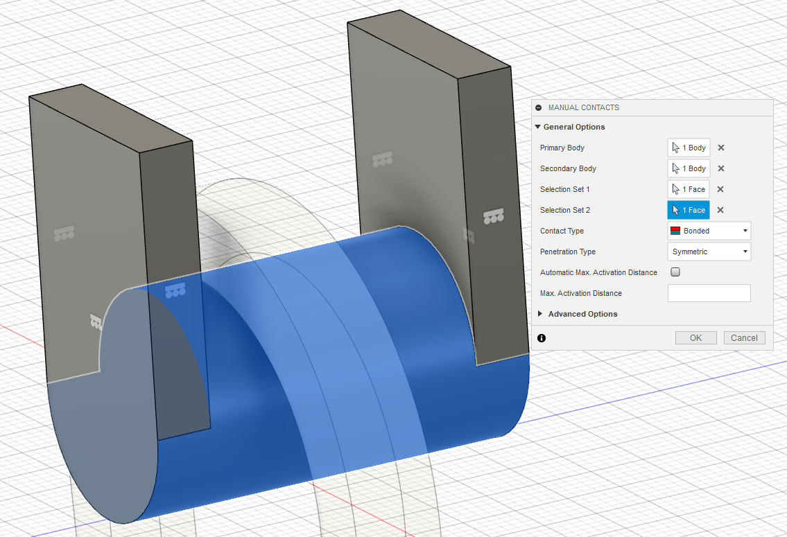
Select the primary body as the carabiner, and the secondary body as the top puller. Selection set 1 is the area they interact, the inside face of the carabiner here. Selection set 2 is just the round face of the puller.
With everything selected, you will see the rest of the menu open for defining the contact type. There are 5 types of contacts.
Bonded - Describes geometry as being welded or glued or otherwise permanently fixed. No penetration, no separation, bodies cannot slide.
Separation - Describes geometry that is separated, but does not slide, such as the gap between a fastener and a hole. No penetration, separation is possible, bodies cannot slide.
Sliding - Describe geometry that can slide, but does not separate, such as scissors, pliers, a vise jaw, or mechanical arm. No penetration, bodies can slide.
**Rough **- No penetration, separation is possible, bodies cannot slide.
Offset Bonded – Same as bonded except the bodies are offset.
For the contact between the carabiner and the puller, there is no penetration, and the geometry should be bonded along that face for the entirety of the simulation. So, the Bonded joint is what should be applied and we can leave the penetration type as symmetric. The other settings can be left alone. Click ok to create the contact, then repeat the same process for the lower puller.
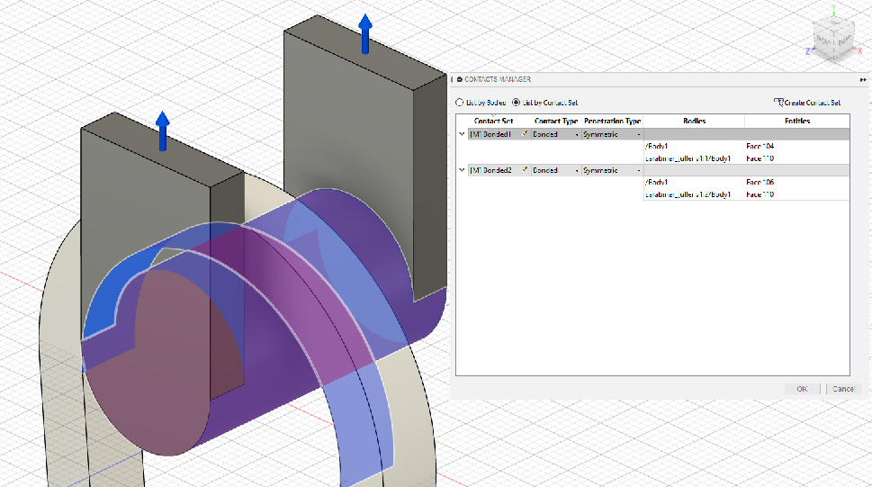
Clicking edit on the contacts section in the tree, we can see the two contacts and where they are applied. The contacts can also be edited here.
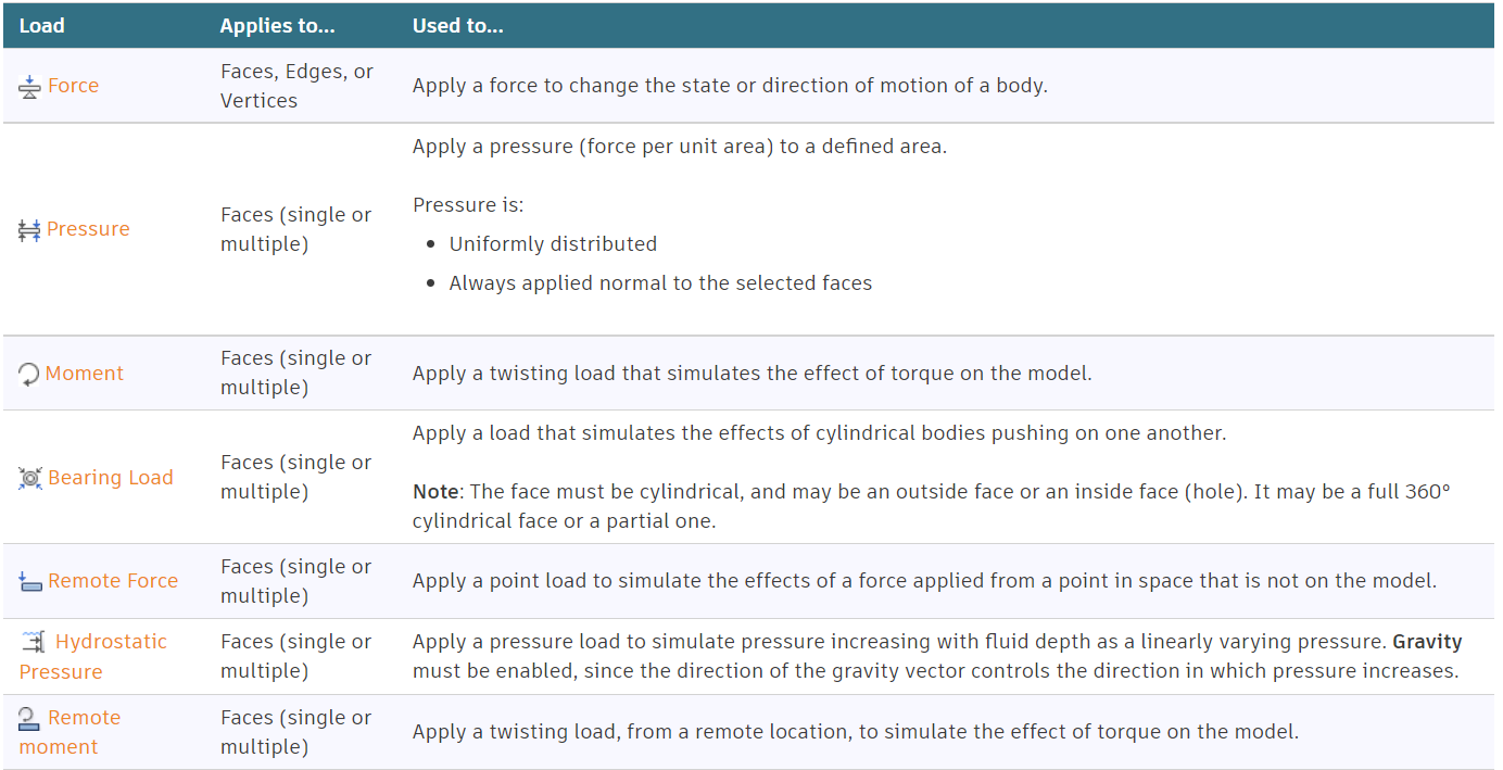
Adding structural loads is the next step, structural loads fall into seven main categories.
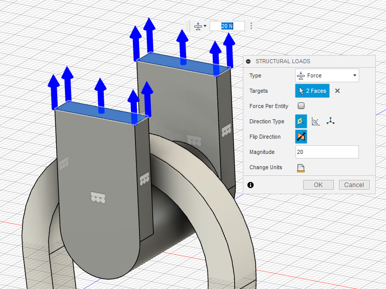
Since we will be ‘pulling’ the puller upwards, we will use a force. Go to loads, create a new structural load (Hotkey L) and select force as the type. The target is the two faces on top of the puller, with the force’s direction being upwards. At this stage, the load is fairly arbitrary as we will be changing it and running multiple simulations. Other simulation types are capable of applying force until failure for a certain load, but for a static stress simulation we need to enter a value. Try and make your best estimate about how much it should hold and you can see how close you are.
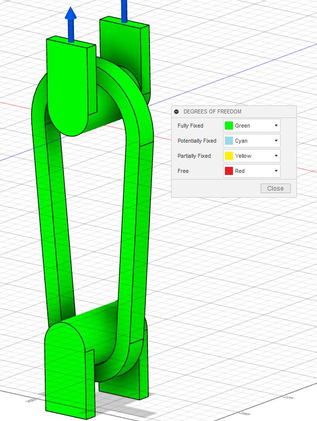
Going back to the Degree of Freedom Tool, make sure everything is green and fully fixed.
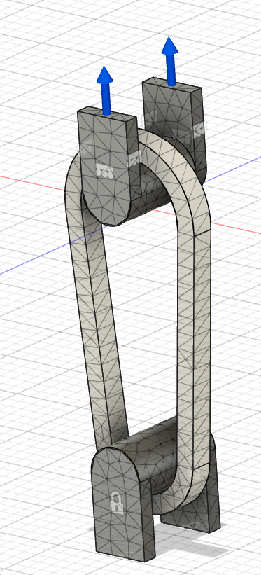
Your simulation is fully set up! Now it’s time for the fun part, meshing and running the study. Right click on mesh and select Mesh Settings, I usually have the slider around the middle for the first run. After clicking ok, right click on Mesh again and select generate mesh, your part should now look something like this.
We can now click the Pre-check icon, on the left side of the solve section. Everything should be good, but if not address the warnings shown. Choose the run locally option in the run simulation tab. Running your simulation on the cloud will take longer than running it on a semi modern laptop (I am running a Lenovo Laptop from 2018, 8000 series i7) and also takes cloud credits.
Now, Finally, we can run our study. This shouldn’t take too long depending on your hardware. Once your simulation has finished, it will probably look something like this. The default graph to show is the safety factor, and clearly the force I chose was well under the failure point.
Safety factor is a measure of how much stronger a design is compared to its working load. Calculated by Stress to Fail / Stress Applied. For example, structural steel in buildings typically has a safety factor of 4-6.
With our results, we need to conduct a reality check on our findings. Fusion creates six plots for a Static Stress simulation. Safety Factor, Stress, Displacement, Reaction Force, Strain, and contact pressure. For our study, we are mainly concerned with Stress, Safety Factor, and Displacement.
Under Load Case1 by the colored graph, click on the box below and select stress in the drop down. You should now see a max and a min stress in MPa, if not click on the inspect tab on the top toolbar and select “Show Min/Max”. We also need to toggle the mesh visibility so we can see it, click on the icon above ‘Display’ on the tool bar. You should now see the stress plotted on your carabiner along with the mesh.
At this stage, I took a close look at the stress on the pullers to make sure nothing is out of the ordinary. Since the stress on them was basically 0, and the stress pattern looked correct, I hid the upper and lower pullers along with the symbols showing the constraints by clicking the eye icon in the model tree. They are no longer required for the study, and block us from seeing the whole carabiner.
During this stage in our study, the main goal is to evaluate your study and make sure there are no obvious discrepancies from your simulation. And making sure your results are aligned with that would happen in the real world. Everything depends on your specific carabiner’s geometry, but I will lay down some basic guidelines.
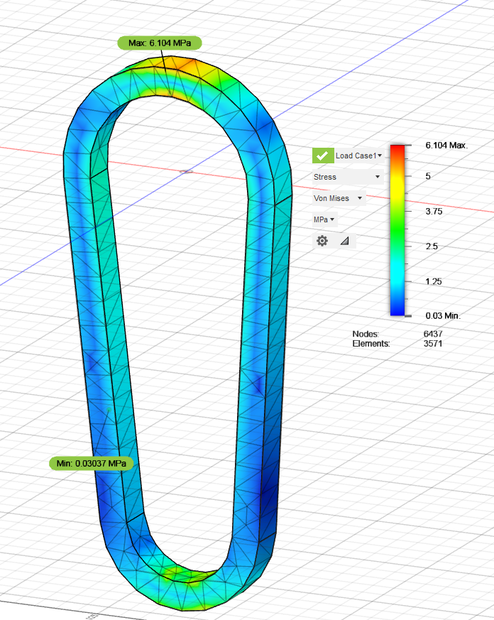
Look at your maximum and minimum stress. Do the values make sense? Are the numbers in the correct order of magnitude? Significantly lower/higher than you expected? You also need to look at the location of the maximum and minimum stress, along with any other locations with stress concentrations.
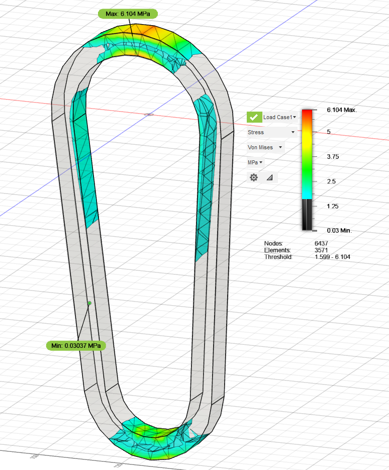
Fusion 360 gives us an amazing tool for visualizing this. If you click on the colored slider to the right, you should see two arrows at the top and bottom. These arrows allow you to only see parts of your model with the corresponding range of stress, helping narrow down stress concentrations.
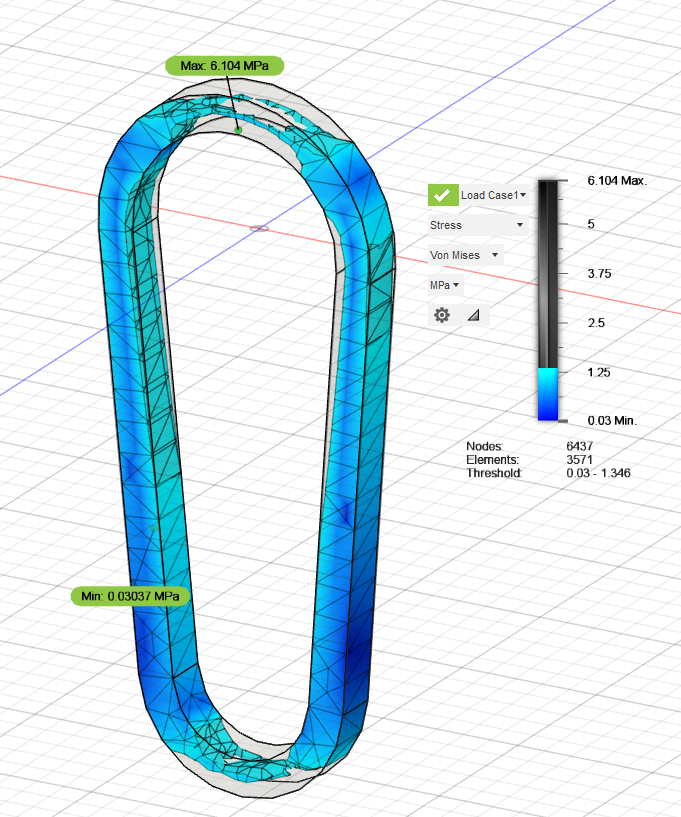
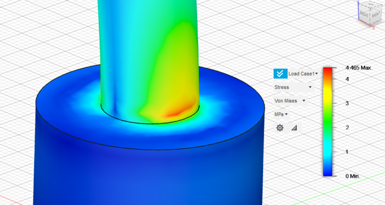
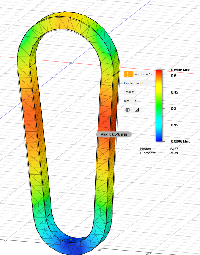
In my model we can see that the max stress is 6.1 MPa, or 885 psi, with an applied load of 40N (9 lbf), Seems reasonable for my load. We can also locate the main stress concentrations, at the top and bottom where the puller is connected, and at the sides of the upper loop. This is a good time to use the lower slider starting at the max stress level and going down, giving you a good idea of how the stress propagates through your carabiner.
Since my first load was clearly too low, I moved up to 120N and ran the simulation again. It might take some trial and error, but you want to hone in on a safety factor of 1. Meaning the force applied is just about what would make it break.
Let’s change the results viewer to view the displacement, the default view is Adjusted displacement. Adjusted just means that the program has made the displacement more dramatic to better show how your model is deforming. Adjusted displacement multiplies the actual displacement by
- The actual displacement should be somewhat low.
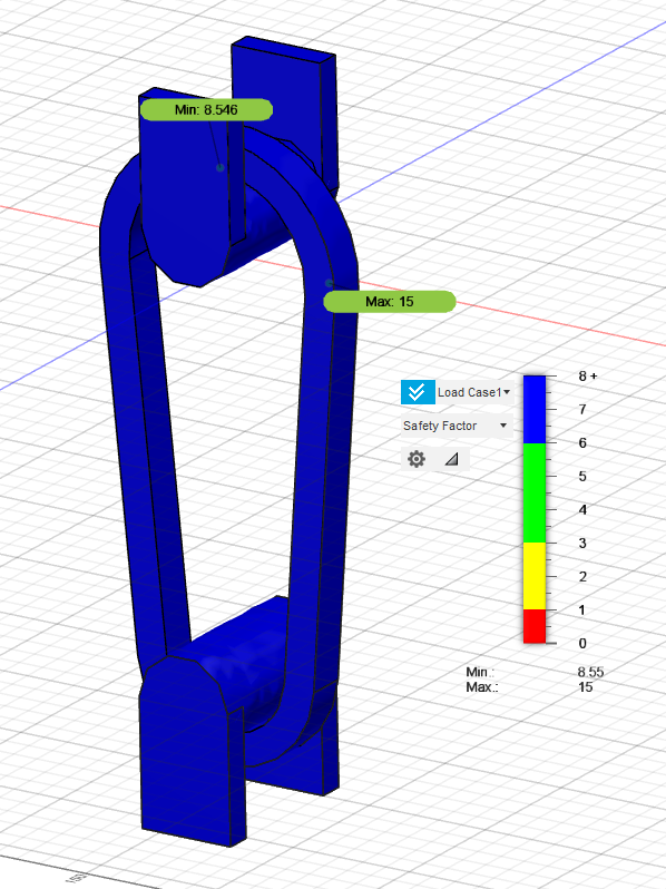
Finally, change the viewer to show the safety factor. This view basically just takes the stress plot and divides the stress at each point by the failure point. So, if the material fails at 30 MPa, at a point with 30 MPa of stress the safety factor would be 1.
Go through the same steps outlined before about checking the simulation for errors and allows for better force averaging. In your previous studies, you might have noticed that your maximum stress was just along one mesh connection. With a finer mesh, the increase in cells allows for structural loads to average over multiple mesh nodes, leading to more accurate results.
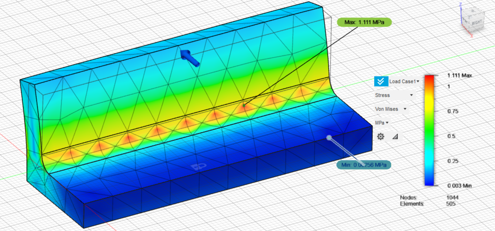
Here, we can see a clear case of where force averaging has not been achieved, leading to imprecise results. The part itself is the same along the X axis, the force is being applied evenly across the entire top face of the part, and the entire bottom face is fixed. Looking at a cross section along the X plane, the cross section is the same, meaning that the resulting stress should be in an even line across the entire part. Instead, the maximum stress is being located only in the middle of the boundary of the mesh cells.
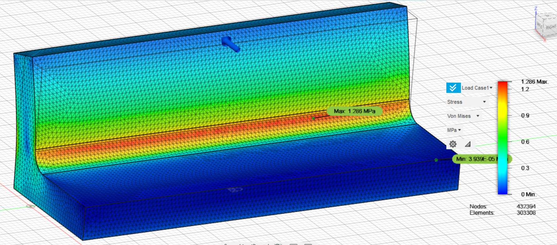
Increasing the mesh, the stress how forms a distinctive line as we would expect (Although I have gone a bit overboard jumping from 1000 nodes to over 400,000).
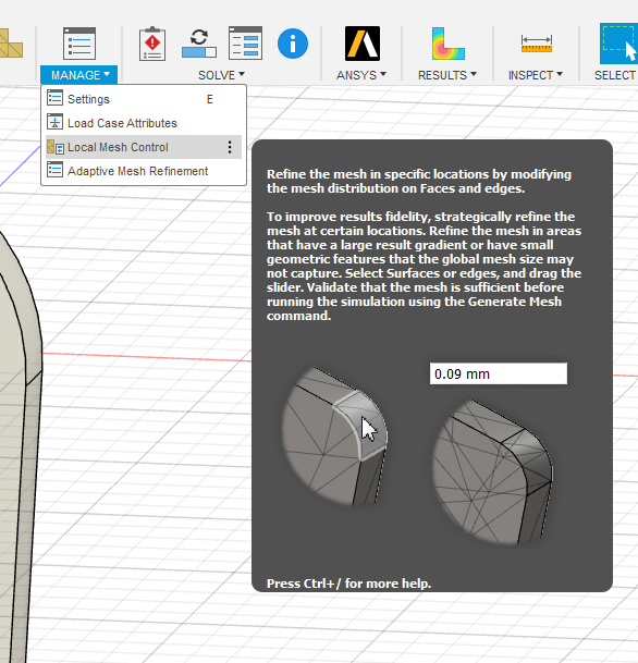
Other than manually lowering the size of your overall mesh, you can also apply local meth controls. Applying mesh control is where you manually set specific areas of the most importance to have a higher mesh, while leaving the mesh in non-critical areas larger.
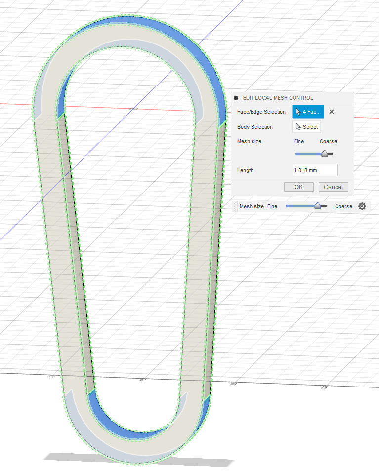
After selecting the local mesh control tool, I selected the curved faces on the top and bottom of the carabiner.
After applying mesh control
Now, you should have all the data you need to analyze your design and make changes if needed. In areas with stress concentrations, try adding more material or changing the geometry of your part (adding/enlarging fillets, shortening connections to make the model stiffer, changing the geometry of high stress areas to better resist the load). For areas with very low stress, you might be able to safety remove material by creating pockets to add weight in other sections.
For iterating your design, Fusion makes it easy to switch from the simulation window back to the simulation window. Depending on how drastic your changes are, you should be able to directly update your simulation, create a mesh of the new design and run it without making any changes to the simulation settings themselves. You can also easily scroll through your iterations on the timeline to compare the first iteration to a updated version.
FEA on the Gate
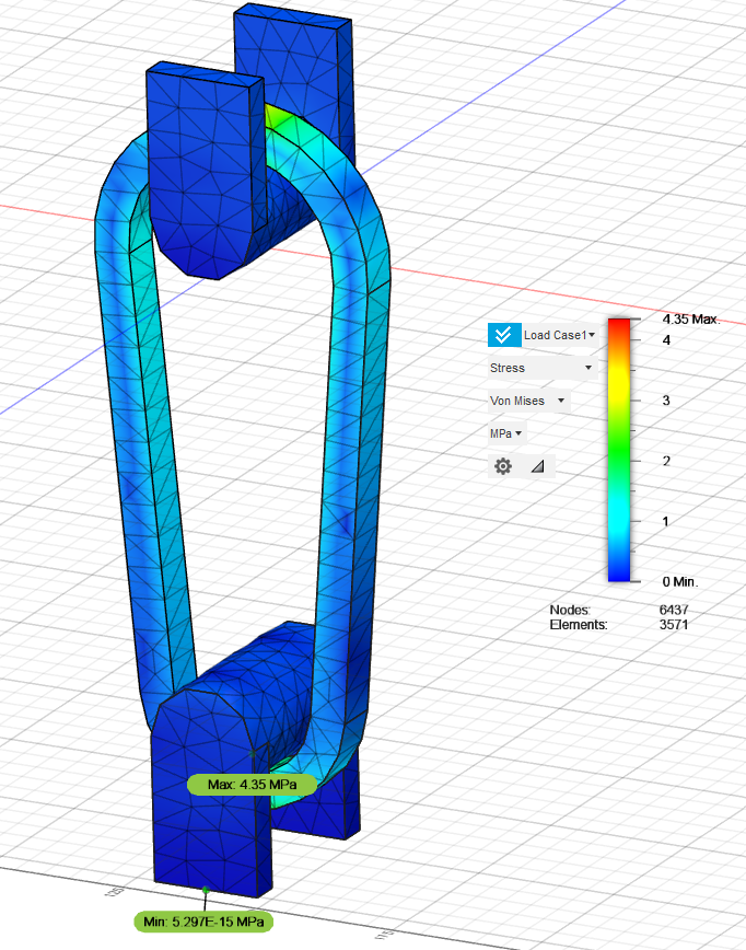
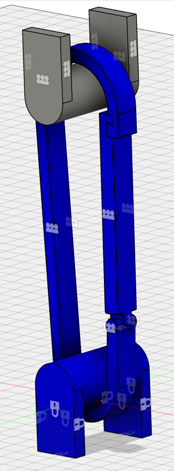
Going back to the design tab, you can now move to your finalized model of your carabiner with your gate. The simulation setup will be the same as before, except we now need to define all of the contacts for the gate itself.
For my gate, that entailed adding bonded contacts where the gate connects with the frame of the carabiner. Along with the contact between the frame, the gate, and the pin.
Since the pin and gate were added, the frictionless constraint should be applied to the sides of them like before to prevent side to side movement.
The pin also needs to be defined as a pin joint in the Constraints section.
Also, if your model includes a spring or separate part for closing the
gate you should consider removing it from the simulation if it does not
play a role in the structural stability of the carabiner.
Before running, check your setup using the DOF as well as the groups tool. In the group view, parts that are not in a group (I.E. not constrained correctly) appear grey and will need to be constrained or the simulation will fail.
Since the full carabiner has more parts and is more complicated, the simulation will take more time to fully solve than before.
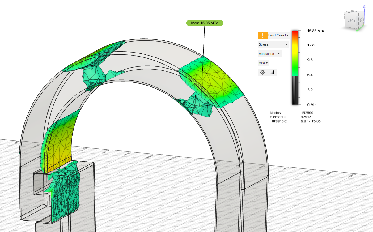
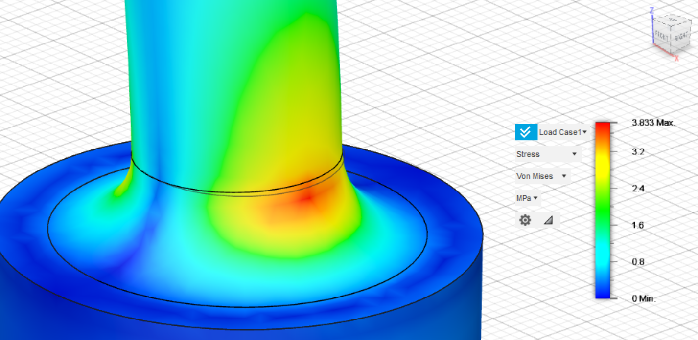
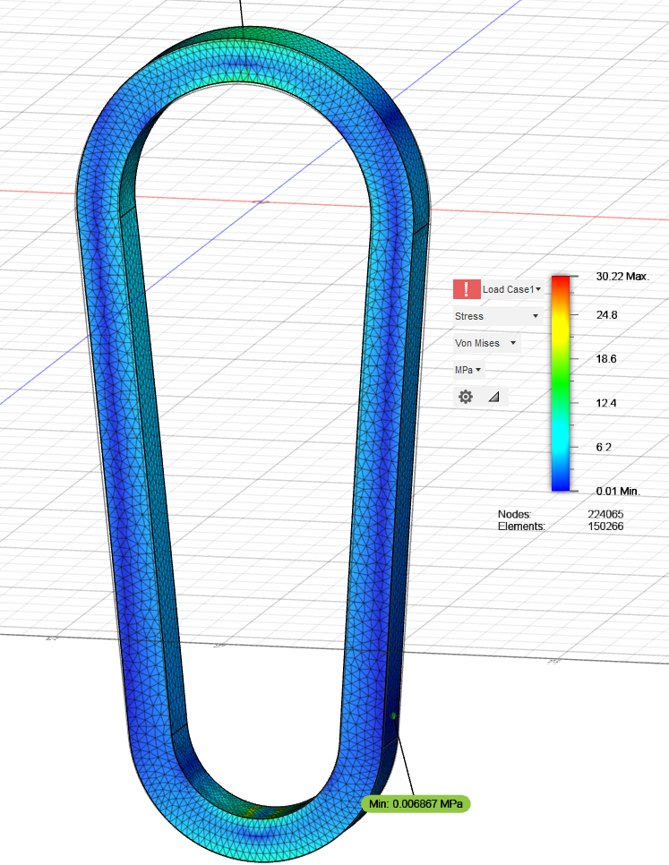
After running my simulation, the failure point is in a similar area as before, with the maximum stresses being near the upper loop. There is also a buildup of stress in the hook itself, but it seemed to hold up slightly better than the rest of the carabiner.
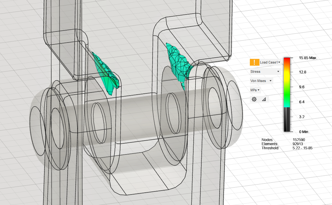
We can also observe how the stress concentrates along the fillets at the bottom of the gate as the carabiner is pulled upwards and deforms.
I hope that my tutorial has been helpful to you. Best of luck.