
1. Kickoff and Design Ideology
1. Kickoff & Introduction
This class intends to flesh out the process of designing and building a CNC (computer numerical control) machine as a gateway to the magic of project based engineering. The project should build skills and impart grander project structure advice along the way. Practical skills covered include: terminology, using CAD (Computer Aided Design), design for manufacturing, concepts in robotics and mechatronics, and much more! On a grander pedestal: we hope that going through these materials will impart wisdom about the thought process behind successfully completing practical engineering projects.
The class is designed to follow my design process step by step, including useful information and knowledge. This structure affords engineers the ability to spread themselves only across the parts they will benefit the most from.
Structure:
-
Introduction and Design Ideology (You’re already here)
- A slightly dry kickoff to design ideology in simple terms of what to do on a high level when starting a project and some thinking exercises.
-
CNC Hardware for Beginners
- A high level overview of terminology, units, electronics, robot control, linear motion, and standards. Brief but targeted understanding of the background requirements for a CNC machine.
-
CAD and Linear Motion
- 3D CAD ramp up from beginner to intermediate as a jumping off point for the more practical half of the materials. With an introduction focusing on visualizing the moments and basic physics concepts and choosing fasteners, bearings, and general hardware.
-
Design for Manufacturing
- School of hard knocks lessons split between more advanced design information and making better CAD. Design information covers an explorative look at the limitations of materials, tolerances, and advice for different forms of manufacturing. Practical side focuses on implementing the new knowledge into existing CAD designs for a new revision.
-
Epilogue, What’s Next, and Why It’s All Important
- Calibration, safety, and software implementation plus machine usage including basic CAM and an overview. Final tidbits about how you can use an “okay” CNC machine to make a better one.
2. Design Ideology
For our purposes, think of engineering as the field of taking a large group of non-intersecting requirements and inputs and developing a way to convert them into a desired output. Simply, this definition reduces big engineering challenges to simple solvable problems. It’s just the knowns and the unknowns. This is important because there are a lot of ways to solve a problem and finding one of the best ones early will save time and money.
I want to set out a few tenets of finishing engineering projects:
-
Simplicity is every engineers best friend
-
Mistakes are inevitable, revisions are the key to successful projects
-
The earlier revisions are made, the faster and cheaper they are
There are no failed projects, only unfinished work. The practical component of this wisdom is that projects that work and work well need to be revised, revised, revised, and revised again. To this end, it is in the engineers best interest to remove as much friction from the process of continued revisions as possible. But keep in mind, revisions need to occur in specific relation to final functionality. It is possible to spend too much time adding too many elements. This is known as feature creep. There is no easy answer of when to add a new feature or to change a feature, but going into a project with a clear list of requirements and sticking to them is essential. Like anything, mistakes and pitfalls mark the path but an open mind and adherence to the tenets I’ve set here are a reasonable start.
How to Start a Project?
It is always best to start with clear intentions. For this CNC project, I started with the big picture: what do I want my final product to do?
Requirements (the robot must…):
-
Be able to draw to a reasonable degree of accuracy within a roughly poster sized work-area. Note: Keeping things vague is okay; but if you aren’t specifying it at the beginning, always assume the easier. In this case, lower accuracy.
-
Have an efficient, minimal, and inexpensive frame.
-
Have three motors in total, one for the x-axis, one for the y-axis, and a third motor for the z-axis to raise and lower the pen.
-
Be easily manufactured with a 3D printer, some basic hex drivers, and a hacksaw i.e. the end user shouldn’t need an advanced fully stocked factory to get through the build.
-
Largely rely on off the shelf electronics to keep costs low and access to online debugging assistance high.
-
Rely on simple modular parts so that if I decide to change the final use case or build a similar machine I don’t have to redesign and print many parts.
- As we’ll get into later, many CNC machines like 3D printers, laser cutters, pen plotters, milling machines, hot foam cutters, etc… rely on common kinematics and electronics. But CNC milling machines (especially the ones that cut metal) have to have far more rigid frames.
-
Have a simple pen holder that is functional and allows for a modest variety of pens. (Pencil/bic up to maybe sharpie).
When composing a similar list of your own, don’t be afraid to add requirements that limit the scope of the project. Requirements like:
-
Can’t cost more than $250 to make
-
Can only use M3 fasteners (or whatever screws or bolts currently owned)
What is the best CAD software?
It is the one that the engineer works best in, but it’s also a trick question. As of my writing this, the only CAD software that can flesh out complex ideas in seconds is old fashioned pen and paper.
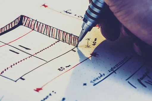
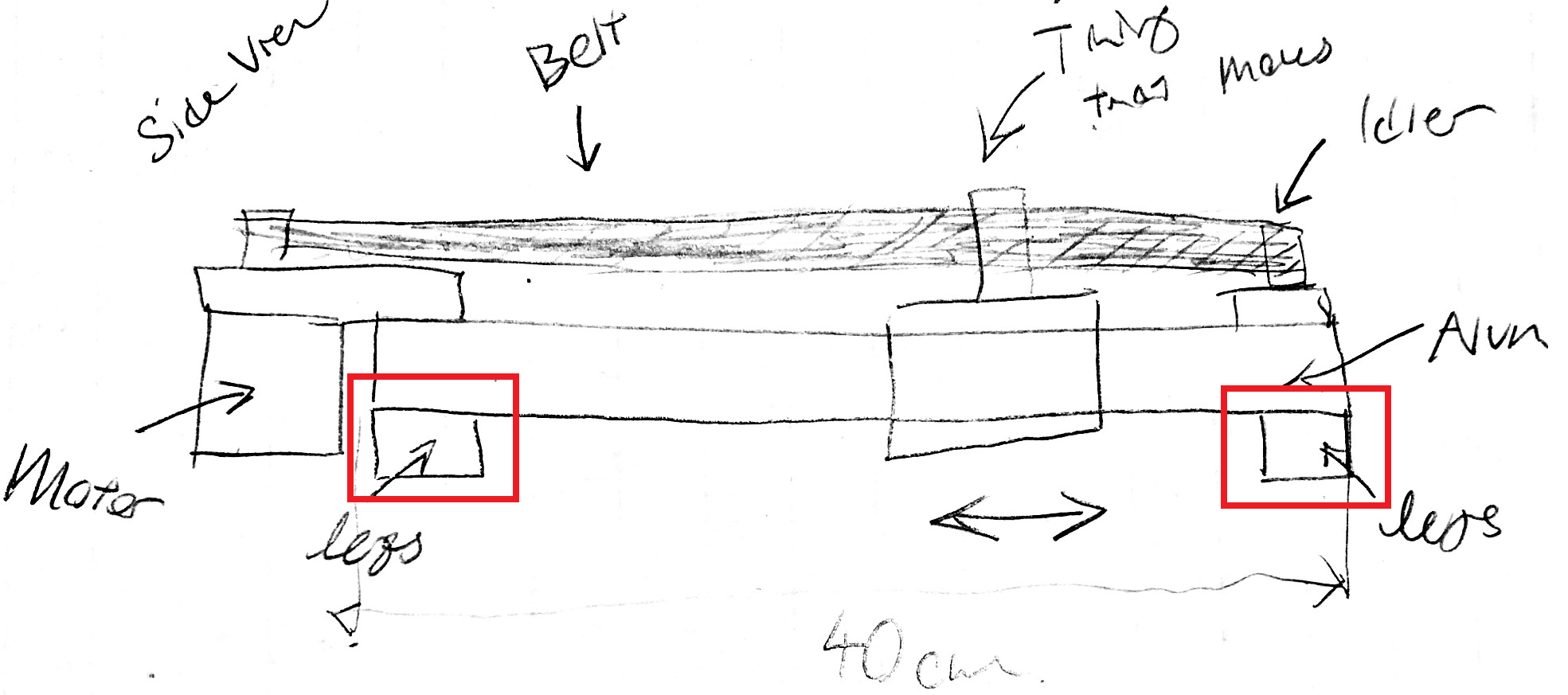
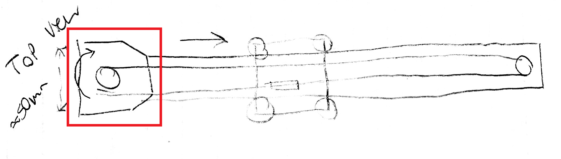
Fig. 1, an example of the level of detail an extremely neat engineering drawing should include. Simple circles, boxes, and arrows with rough dimensions should suffice. Sketches like this are powerful but can only function when the designer finds their own work legible.
Any engineering project should start with documentation on the specific needs, both functionally and physically. The fun work can only begin with a clear list of objectives and constraints in place. The ideas phase should be as simple as thinking about different novel solutions and drawing them on paper. Taking some time to visualize motion, key steps in the function, the assembly, and manufacturing quickly aids the selection of ideas that are more practical.
The cost of any changes to a project go up exponentially as projects gain momentum and a base of research. Which is why cheap and fast tools like this are so essential.
3. An Application
In one of its most simple forms, any CNC machine(such as a laser cutter, 3D printer, robot arm, milling machine etc) is just a device developed to move around in a certain coordinate plane. Note figure two and consider how many motors (or manipulators) it would take to move a robot from the origin to the point P(3,5).

Fig. 2 A Cartesian Coordinate plane with two axes (x & y). Note the variation in possible locations that can be reached within the marked bounds of 0-10 on each axis.
If you only need to move between the two points P(3,5) and the origin, that can easily be achieved with a single stationary motor. This single motor configuration can be achieved in any number of ways but two examples are a motor attached to a leadscrew (turning the rotational motion into linear motion) or a motor placed between the two points with an armature or reach allowing a purely spinning motion to move between the points. It can be easy to overthink challenges and hard to leave behind those assumptions. With two motors we have a lot more freedom, we can access an arbitrary number of spaces in this coordinate plane. This distinction is very important as cases where we don’t need the versatility offered by the extra motor can be greatly simplified with its absence.
4. An Exercise
Exercise: Given a two-dimensional coordinate plane (shown in figure 2), design a simple mechanical system that can reach any given point using its own motors. Note at this point, all “designs” should take the form of a basic sketch showing the functionality and placement of components. Then design two more different systems to fulfill the same criteria. With three simple designs drawn out, compare them. Which would you rather make? Do you think some will be easier to program than others? Try to articulate specific reasons why some are better or worse. (Hint: Use paper and if you get stuck try thinking about cars navigating from top down, polar coordinate systems, or vectors. Don’t spend more than five minutes on this if you aren’t enjoying it!)
2. CNC Hardware for Beginners
1. Introduction to Hardware and Movement
This lesson is about thinking of the challenges involved in all levels of getting objects from one discrete location to another with repeatability. The main focus of this class is linear automation systems that require getting to an arbitrary number of positions along a certain route or within the size constraints of the machine. I will also be touching on some elegant solutions to scenarios in automation that only require repeatable translation between specific a and b positions.
For this project specifically, we already have a list of design constraints or requirements drawn together in part one and at least a few ideas of how to actualize a design. The next step for us is to bring those paper drawings into the real world with an understanding of drive systems and hardware.
Learning the linear motion lingo
Most linear motion, movement in a straight line for controlled distances, is a combination of a motor, a way to convert rotation to desired translation, and a mechanical structure to support the moving parts and whatever is being moved. Typically the conversion of rotational to linear motion occurs using either lead screws or belts, but there are hybrids and many other possible solutions.
2. Hardware
Belts or Timing Belts
The big advantage of belts is their low cost and versatility. Belts are extremely cheap and don’t have special shipping concerns (unlike lead screws which can bend easily making them useless). They are almost perfect. Before I ruin the magic, check your understanding by looking at fig. 3 below. The main limitation of a belt is that it is not rigid. Some CNC milling machines will still have them, but they are for cutting very soft materials. In a milling machine, when the cutting starts, excessive forces can cause the belt to stretch and the machine to lose accuracy. Flex creates the enemy of the CNC milling machine: backlash. Backlash is the play between components in a mechanical system and the best CNCs need to maintain almost none.
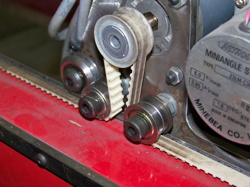
Fig. 3 a linear motion system driven by a belt. The ends of the belt on the right and left sides are fixed so as the motor (the large, central, silver wheel) turns, pulling the axis in either a left or right direction.
Okay you may ask… What about a belt like thing that isn’t slippery or flexible? Some kind of metal belt like thing would be interesting.
Chain
Great point. But think about how a chain works. Metal plates bolted together rigidly in specific link sizes. Can you guess what problems I’m going to bring up? The three problems are tensioning, efficiency, and noise. Exact distances between the sprockets are difficult to achieve with chains because the loop sizes are “quantised” by the individual links. This means that the chain often won’t be the exact right size for a given system. This creates the problem of how to tension the chain while maintaining efficiency. Really tight chain will have the least play but it will also be the hardest to turn. Fundamentally, the chain is designed to be a high power and very efficient transfer system, but it suffers at higher RPMs because of the number of moving parts and it isn’t designed to transfer loads without backlash. But with all of that said, there are a lot of smart engineers like you who have found work arounds that make chain work. Checkout the maslow CNC in fig. 4 which uses a carefully weighted gantry to ensure the chain keeps the right tension in action. Maslow’s main consideration with adopting a chain drive is their need for ultra cheap mechanical components in a very large form factor.
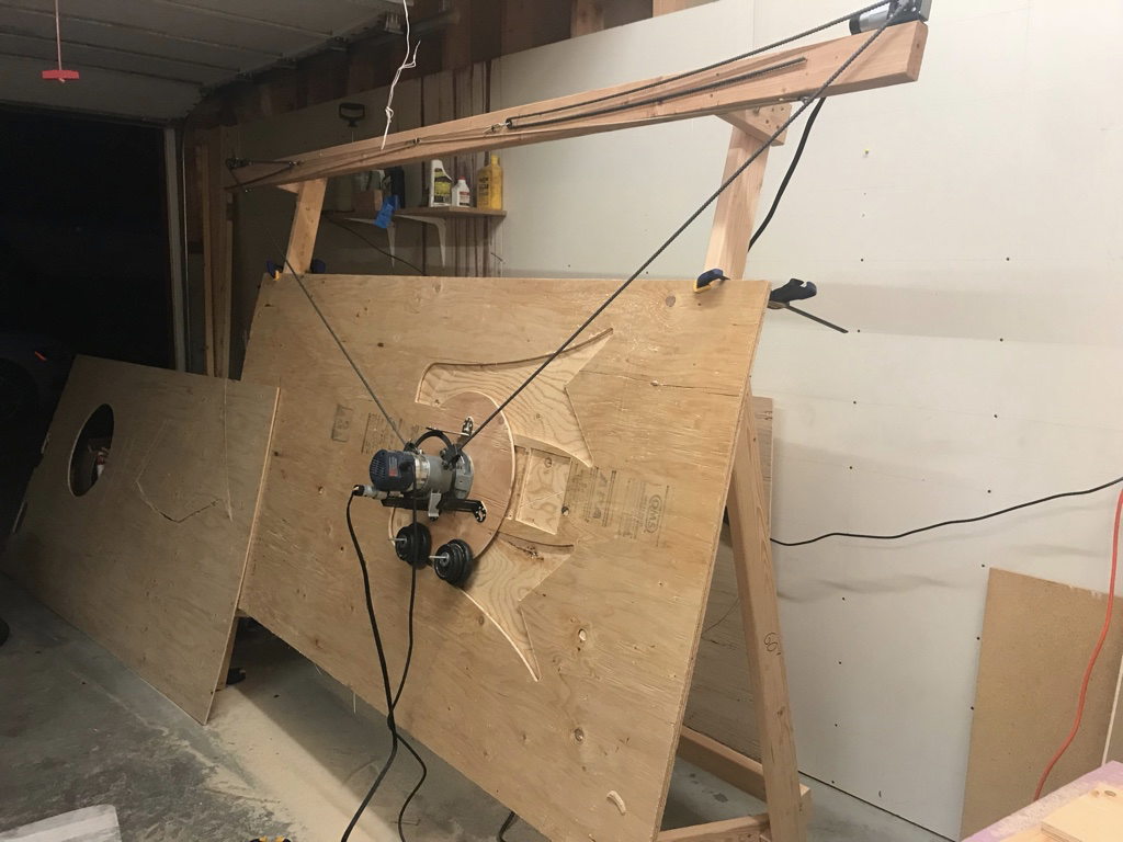
Fig 4. Maslow CNC machine which uses a weighted freehanding gantry and chains that are sprung and weighted for tensioning. It is designed to be an inexpensive huge CNC mill for wood.
Leadscrews and threaded rods
Screws are typically defined with two numbers, the diameter and the slope of the helix pattern. The latter is often discussed as the number of “teeth” per distance. This consideration is important because it is part of the mechanical advantage the machine has. If you have a very fine pitch or high rate of the teeth the machine will exert much more torque on the workpiece but it will also move much slower. If this doesn’t make sense, think of the screw and its pitch like a gear ratio. The pitch is really just a way of saying how far the screw will force a nut to move per single rotation of the screw. The classic dilemma: speed or power. The reason that a typical bolt-esqe screw isn’t often used in CNC machining is because of backlash. Screws are really bolts and bolts don’t need to be very precise, they are designed to be tightened till they bind and hold in place. Bolts and nuts have a lot of play. If you hold a bolt with an engaged nut in hand, you can quite easily notice that the nut can slide up and down slightly. This means that the rotation of the screw doesn’t perfectly correlate to the final nut position relative to the bolt. In figure 5, we can see why this happens. The nut has to be made larger than the screw for it to engage on the thread and that means that the screw has to re-engage the nut each time it changes directions. That means that over time, the nut isn’t moving along the thread as much as the thread is moving. This is backlash in action again. Figure 6 shows a nut engaging each direction of the screw using a spring.
The spring forces the two nuts apart and keeps them engaged so as the screw rotates the nut moves at the same rate even during direction changes. This is called an anti-backlash nut and it’s a screw-like system that was standard in tools like requiring linear motion for a very long time. But there is still something better out there for wonderful precision and power.
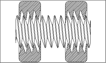
Fig. 5 shows how a nut can only be engaged in one direction at a time, and when the direction of the thread changes there is some lost linear motion.
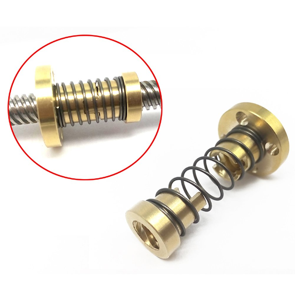
Fig. 6 shows two sprung nuts, in much the same orientation as the nuts in figure x but as a more tangible solid part.
Ball Screws
The undisputed king of CNC is the ball screw. Ball screws work by creating a totally different kind of engagement between a “nut” and the helical slot. Instead of the sharp screw edges, ball screws use smooth soft semicircular helical surfaces. They get the name from their intermediary ball bearings which lie between the “screw” and the “nut”. In a ball screw system the nut and the screw never actually touch. As the ball screw rotates the nut is moved along by a series of small ball bearings that move with the screw until they reach the bottom of the nut where they are re-channeled around the outside back to the top. This design reduces friction and backlash as the tolerances between two round edges are easier to control.
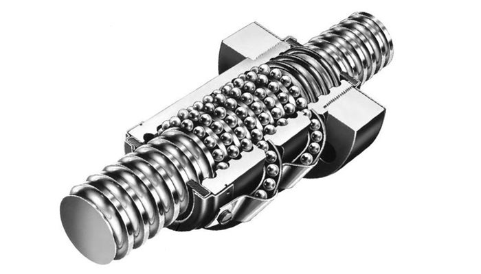
Fig. 7 depicts the ball bearing orientation inside a ball screw nut.
Quick note on how we join motor shafts to lead screws, threaded rods, & ballscrews.
Couplings
The world is far from perfect and no rotating bodies will ever line up perfectly. It is very important to consider how the rotational motors will actually connect to the linear rods. This is less of a concern with belts because they are naturally flexible and work to remove much of these problems on their own. On a lot of early 3D printers, makers just shoved aquarium tubing on the motor shaft and the linear rod and then added many zip ties. Which actually works very well as long as there is a force, like gravity, holding the rod down on the motor.
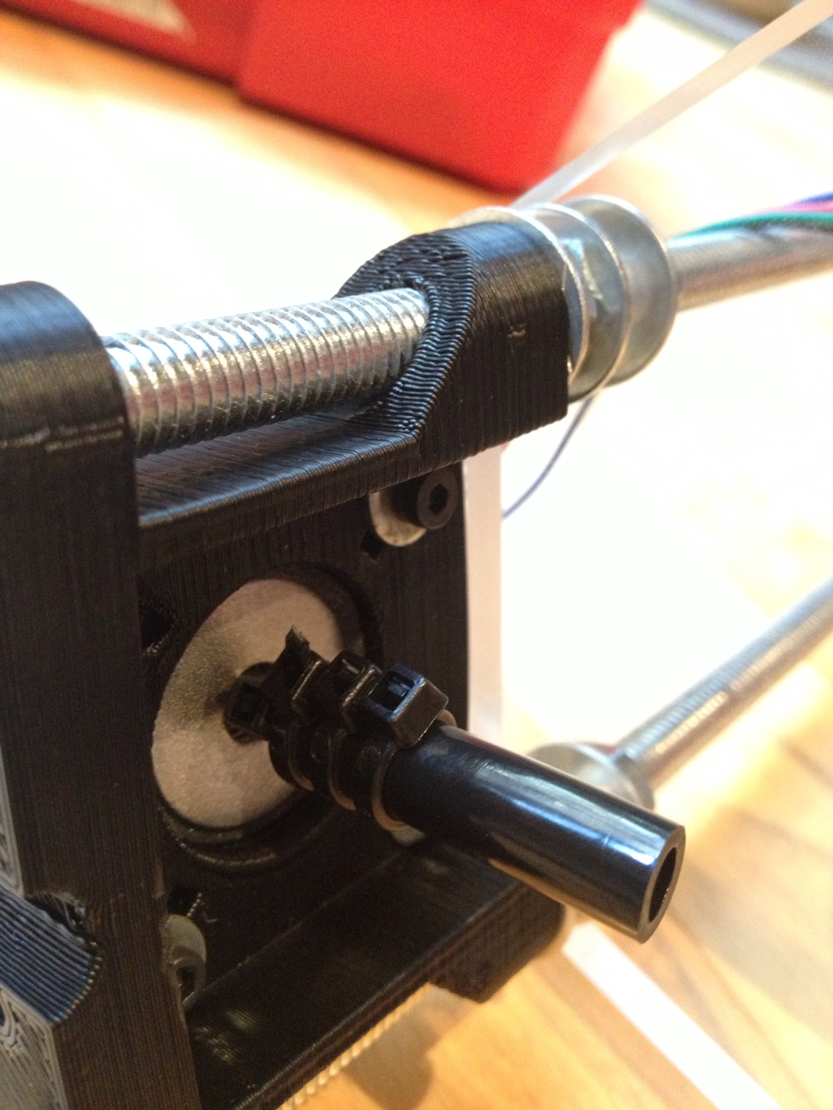
Fig 8, an adequate coupling built from zip ties and flexible tubing.
There are slightly better ways to couple linear motion components once you have a 3D printer available.
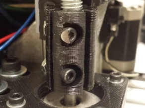
Fig 9, shows a simple and fairly rigid 3D printed coupling.
The next tier of coupling quality on this kind of project are spring or flexible coupling which are manufactured to a higher quality professionally and are, despite their name, still more rigid than either of the previous mentions. The reason there are helical cuts that make it springy are to account for imperfect alignment between the shaft and screw.
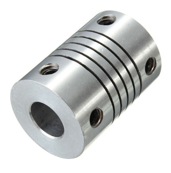
Fig 10, is a cheap and widely available flexible coupling
Finally, one of the best coupler designs is a semi-flexible oldham coupling. They have a distinct look, the stark color contrast of the brushed aluminum finish and a bright softer middle.
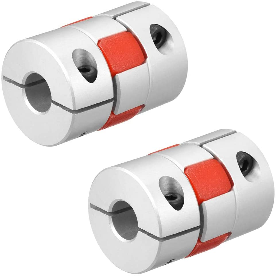
Fig. 11, an oldham style semi-flexible coupling. Note the red middle is a rubber material and typically called the spider.
This brief jaunt into the magical realm of couplings is included as a capstone for building linear motion with leadscrews. Good couplings are important to get the best out of a leadscrew or ball screw. We are now at our first real hardware crossroads and I want to take this opportunity to continue to highlight the variance of engineering solutions, each with their own reward structure.
3. The Right Linear Motion System for You
In order to decide on a linear motion system it’s important to refer back to the design constraints we set out earlier. This should always be the baseline in making an important decision.
Here are the relevant parts from our design requirements list:
-
Have an efficient, minimal, and inexpensive frame.
-
Be easily manufactured with a 3D printer, some basic hex drivers, and a hacksaw i.e. the end user shouldn’t need an advanced fully stocked factory to get through the build.
-
Largely rely on off the shelf electronics to keep costs low and access to online debugging assistance high.
-
Rely on simple modular parts so that if I decide to change the final use case or build a similar machine I don’t have to redesign and print many parts.
With these considerations in mind I settled on the cheap and simple belts for my CNC design. I don’t need the force that stronger linear motion can lay down and I don’t really want the added weight either. I am also going to start thinking about how I want to ensure smooth sideways motion. What kind of bearing system am I going to use? I want to take an idea from other low cost CNC designs and use my frame as a linear bearing. This is getting more and more popular with 3D printer designs. Typically these motion systems work using extruded aluminum frame components and special rubber coated bearings very similar to skate bearings to ride in tracks along the framing materials. This means I can have a fairly rigid aluminum frame without having to deal with as many different parts.
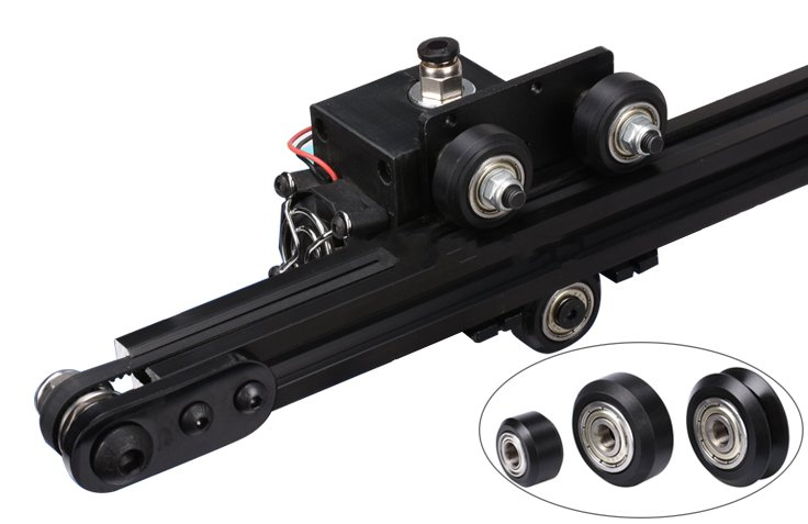
Fig 12, shows a linear slide built with roller bearings in aluminum extrusion.
4. What does a mill look like electrically? What will yours look like?
The robot or machine we’re constructing is powered by motors and electronics so how do we select them and why should we choose one style over any other? Firstly it’s important to discuss motors. Motors are probably the most important choice when it comes to electrical configuration of your CNC project. There are AC and DC motors. For the scope of this project we can focus on DC motors. AC motors are more widely used in industry and appliances but are more expensive to control and don’t work as well with a dynamic range of speeds. DC motors are cheap and ubiquitous in the DIY community. The types of DC motors to know are: brushed DC motors, brushless DC motors, DC servomotors, and DC stepper motors. Brushed DC motors, which is what most people mean when they say “DC motors”, have no intrinsic position control. You can vary the power into them, but need an external sensor for accurate control. Brushless motors are much the same, but more efficient and often much faster and more powerful. This can be a winning combination, but to use it in this application you’ll still need a precise external sensor to check the position. Typically people use either a potentiometer or an encoder. DC servomotors and steppers both have precise position control so they are going to be best for this application. As a cost of their position control, they both lack power and torque compared to similar brushed/brushless motors.
Servos are really fast and can be dialed in to be precise but most aren’t designed for long periods of constant load and lose all precision when they aren’t limited to 180 degrees of rotation. Steppers are pretty much the perfect motor for this kind of system. Stepper motors can move forward or backward in “steps”, and they generally have 200 steps per full rotation meaning they can move precisely in 1.8 degree increments. What makes this motor precise is that we can choose which of these steps to move to at any time. Stepper controllers can get much more precision by moving to spots between these steps to allow for finer position control. This is called microstepping and is important if you want to improve the accuracy of your machine. I will note that this brief description is nowhere near a good enough look at motors for wider project usage or even to gain the important wisdom on how these motors work. Specifically, for the necessary deeper dive I highly recommend the book “Motors for Makers: A Guide to Steppers, Servos, and Other Electrical Machines[1]”.
So I’m using stepper motors and I’ve explained why, but what do we need to use to control steppers in the first place? It can be a little complicated but really it will always be a thing that converts power and digital control wires to physical motion, and something to send those digital controls to that converter.
The Big picture
There are three main parts to an operational CNC machine. Firstly, there is the CNC milling machine itself, the thing we’ve been designing so far with its motors, linear slides, and spindle. Secondly, there is a “control box” that’s in charge of physically telling the motors what to do. This control box is typically powered by an embedded microcontroller that controls the motors (through motor driver circuits) while taking commands from the third and final component, a computer that runs special software to generate coordinates that the machine can understand. There are many other potential inputs that go into the embedded microcontroller. There will likely be “end stops” or limit switches for each axis that zeros the machine so it knows the exact position of each axis each time it powers up. I also like to have an external emergency stop or E-STOP. Otherwise known as: a big red panic button that occasionally has to be stressfully slammed to stop the machine.
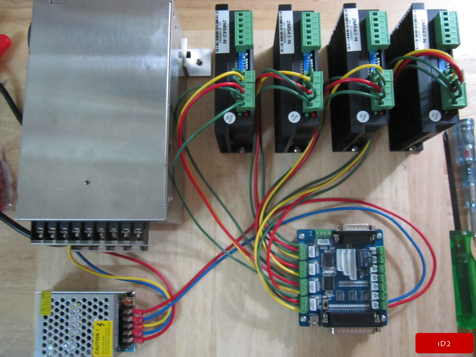
Fig 13, is an assembly of a CNC electronics stack featuring power supplies (left), four stepper drivers (top right), and a microcontroller (bottom right). It is missing a computer sending cam or instructions directly to the microcontroller
Motors and Stepper Drivers
For the reasons we discussed earlier, in the hobby space, the vast majority of CNC machines use DC stepper motors. The physics and exact functionality of these motors isn’t extremely important. What is important is that stepper motors have some behavioral quirks that other motors don’t share. Firstly, stepper motors have peak torque at a standstill andlose torque as their RPM increases. Secondly, there is a much smaller variety of motors due to the standards created by the National Electrical Manufacturers Association or NEMA. They use three standard sizes for projects: NEMA 17, NEMA 23, and NEMA 34. The numbers correspond to motor width in tenths of inches. The NEMA 17 motor is 1.7” or 1.7 inches across.
| Motor Type: | Motor Size: | Typical Torque:* | Price Per: | Stepper Driver Price: |
|---|---|---|---|---|
| NEMA 17 | 1.7” | 60 Ncm | $13.99 | $2.00 |
| NEMA 23 | 2.3” | 190 Ncm | $25.99 | $24.00 |
| NEMA 34 | 3.4” | 1200 Ncm | $69.99 | $50.00 |
Table 1. Note that the typical torque is dependent on the length of the motor. Also note that each stepper motor doubles the cost of the last but has substantially higher torque per dollar.
Nema 17s are pretty small and weak but their popularity among 3D printer designers has massively brought their costs down making them a focus for the requirements of this class. All NEMA motors are available in a number of different depths which grant more customization and overhead on the typical torque numbers from the table. Note that depth corresponds to the physical area of the magnetic surfaces inside the motor so they can apply more force. For this drawing robot project, there are no cutting forces so we might as well opt for the cheap and easy option of the NEMA 17.
3. CAD and Linear Motion
1. Introduction
We are finally going to choose CAD software and start moving things toward the physical realm. I am using Fusion 360 in this section but much of the information should hold for other CAD softwares.
Structure:
CAD and Linear Motion
-
An overview of working in Fusion
-
3D CAD ramp from beginner to intermediate and a jumping off point for the more practical half of the materials.
-
A few tips
-
Discussion of several devices and the complexity of making full 3D models
Note: The best CAD software is doodling on paper as discussed before as it is the fastest way to begin to flesh out ideas. The second best CAD software is the one you are most comfortable with. I have used several and find that Fusion 360 is the least terrible. I can work quickly in it and find many of its features very convenient, so it is the focus for this section. Even if you want to use solidworks or another software package, try to find some of the tools I recommend here as many software packages will have them and they are very good at saving time.
2. Working In Fusion
When you first open Fusion 360, after you are prompted to sign in you will see a home screen that looks like the one below. Minus the crudely drawn colorful rectangles of course. The rectangles are placed on the screenshot below for a brief explanation of all of the parts they represent. The pink rectangle at the top is the least important to explain. All of the icons in the pink rectangle have an information dialog box that will pop up if you hover the mouseover them, meaning that they don’t really need to be explained in great detail here. The icons are all about making changes to or formulating the design. The blue and magenta boxes (in the upper left and right corners) and the brown box at the bottom are all about observing the file and it’s parts and history. The green box positioned in the lower center is the display and interaction settings block which is the place to go for customizing input controls, display colors, and the view style.
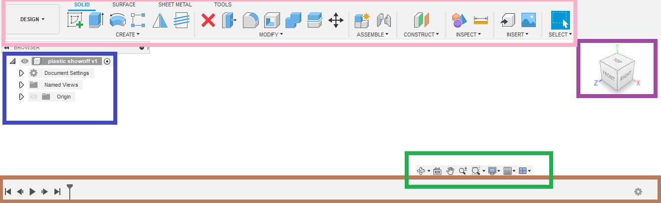
The brown box at the bottom encapsulates the timeline of a design file. This will track changes as they occur. It is empty or unpopulated at the moment because the file has just been opened. The timeline allows you to go back in the file history and make changes at different points. The system will then regenerate a new timeline with those changes, often without needing to fix merge conflicts. This is huge. If you make a mistake, you can simply go back in time, fix it and then the part(s) will totally regenerate from that point without further changes.
The purple box, located in the upper right corner is the view cube. You can click on any of its sides that are visible to move the camera to that perspective. Generally it is more useful to click and drag on a face to move the camera around for more fine control. If you do this before you’ve actually made any geometry in Fusion, the results will be pretty uninteresting.
The blue box shows all the entities that exist in the file. These entities are generally restricted to:
-
Sketches
- These are the flat planes with sketch geometry on them that make up the bases of all of the 3D geometry in your CAD file.
-
Components & Bodies
-
Understanding the difference between components and bodies and the broader reasoning for those differences is key to understanding the difference between Fusion and other CAD softwares.
-
In fusion, no matter how many parts are in an assembly, it all takes place in one file. The way this one file (generally .f3d) organizes parts and sub assemblies is within the confines of components and bodies. A body is any self contained piece of 3D geometry. Any number of bodies can make up a component, but generally it is only one body per component and then, you simply add more components when you have more bodies. A component is kind of like a folder for bodies. But like folders a component can have a component or multiple inside it. This is how sub assemblies are organized.
-
For a more in depth and user friendly explanation of this dynamic: Fusion 360 Components & Bodies for New Designers - Fusion 360 Blog (autodesk.com)
-
-
Joints (sometimes called constraints in other CAD softwares)
-
Joints are user created rules defining how parts interact with each other. If you want a bolt to stay in a hole, you have to constrain it there. Joints can also be used to simulate motion. You can define the gear ratio between rotating bodies so when one is rotated the other will rotate the correct amount relative.
-
More details: Joints in Fusion 360: A Comprehensive Tutorial! FF117 - YouTube
-
-
Construction Geometry (think planes that can be sketched on)
-
Construction geometry is an advanced tool for accessing parts of a CAD file that can be difficult to get to otherwise. Much like scaffolding in real life. Construction geometry is advanced for the scope of most of our work but I think it’s important to touch on here.
-
For reference later: Hacker Lab Coworking & Makerspace - Using Construction Planes in Fusion 360 - Bringing your sketches to new heights | Hackerlab Global
-
3. A Few Tips
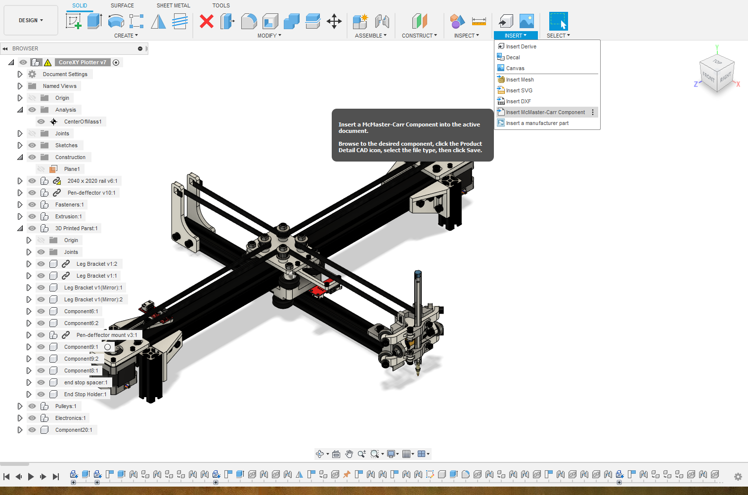
Save time by grabbing CAD files of standard parts. The full McMaster-Carr 3D file catalogue is available at a few clicks of the mouse. Having standard hardware from bolts to wheels to linear motion components can save tons of time.
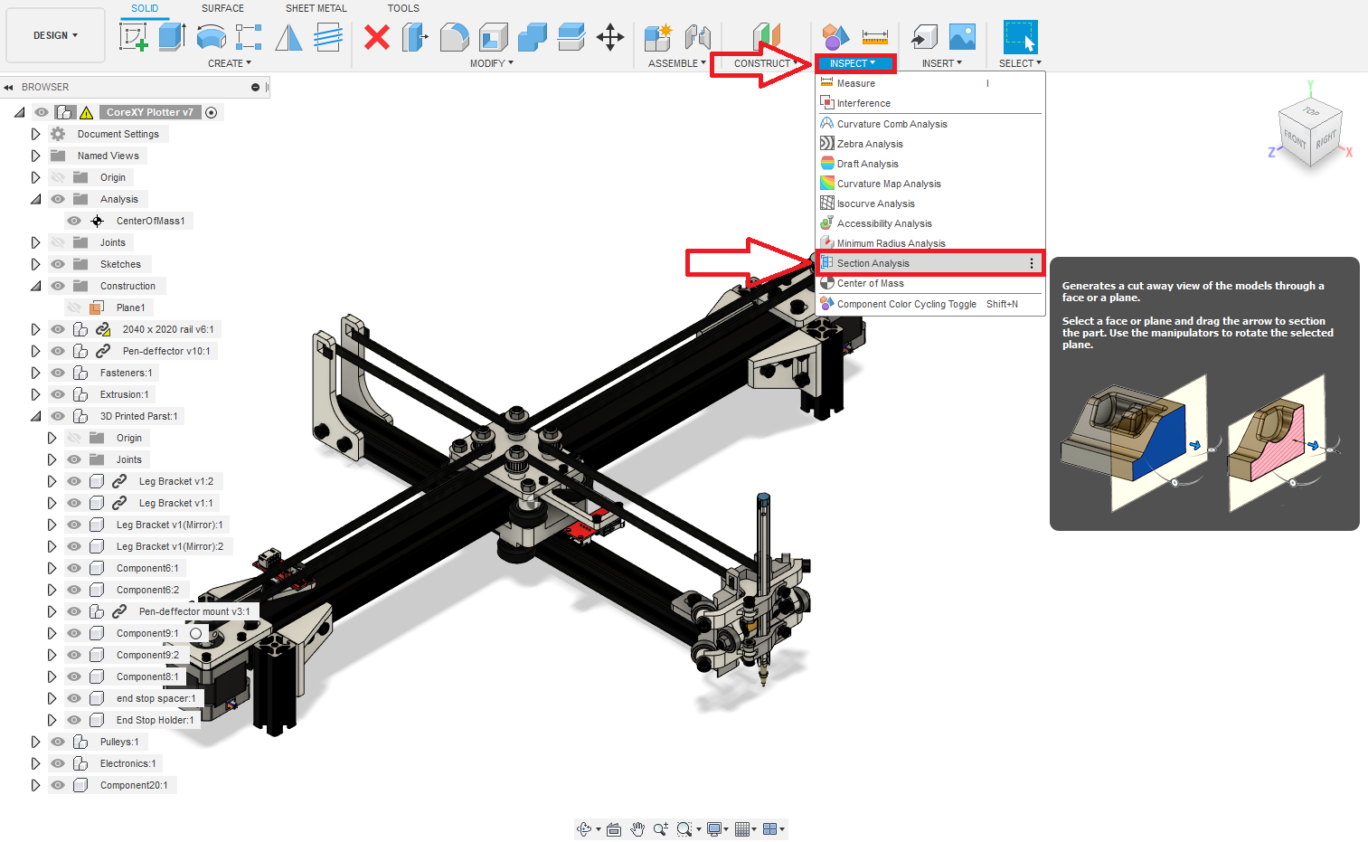
Sectional analysis. Use a plane to visualize the part cut into sections so you can check that things fit well after they’ve been assembled.
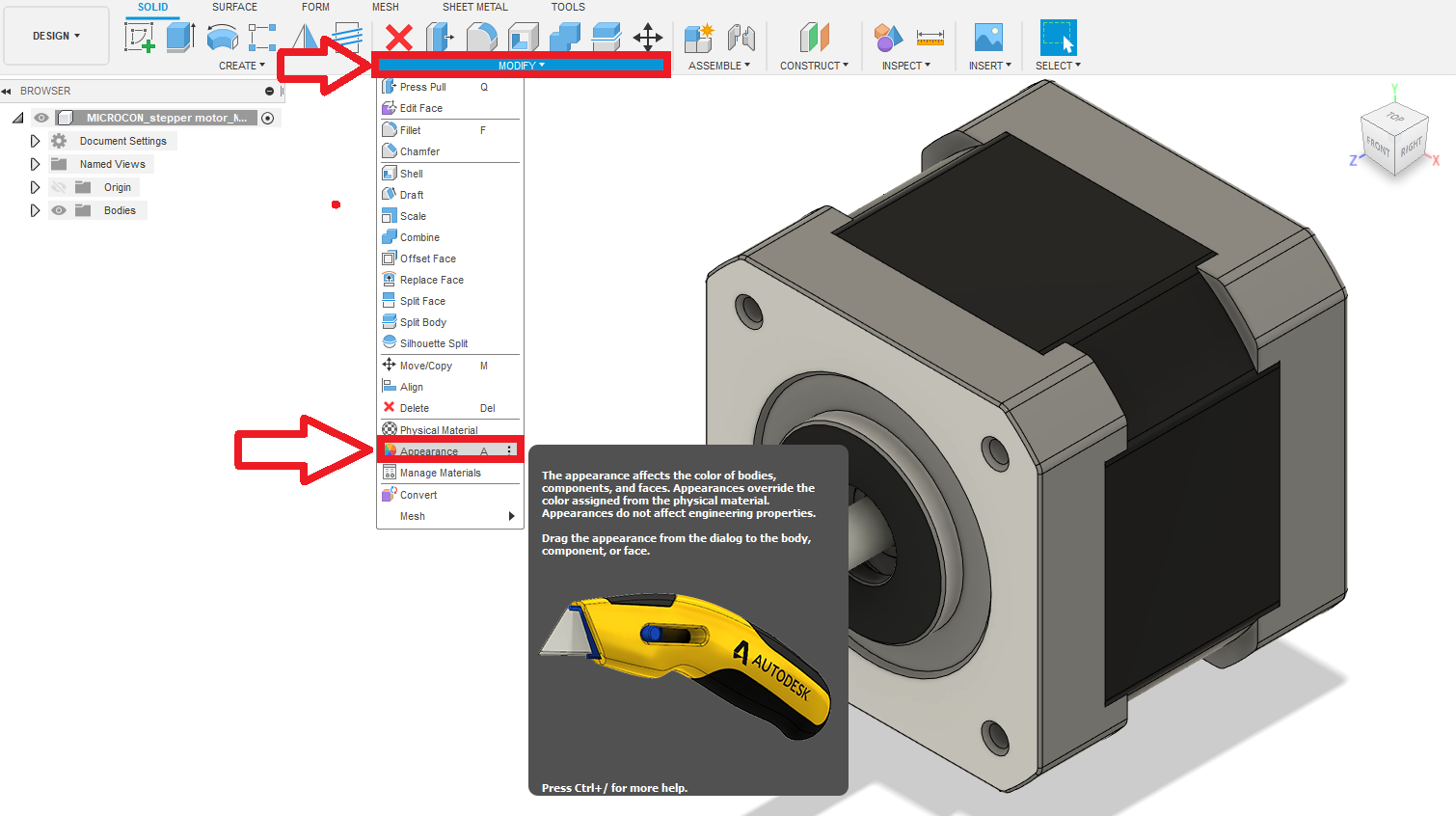
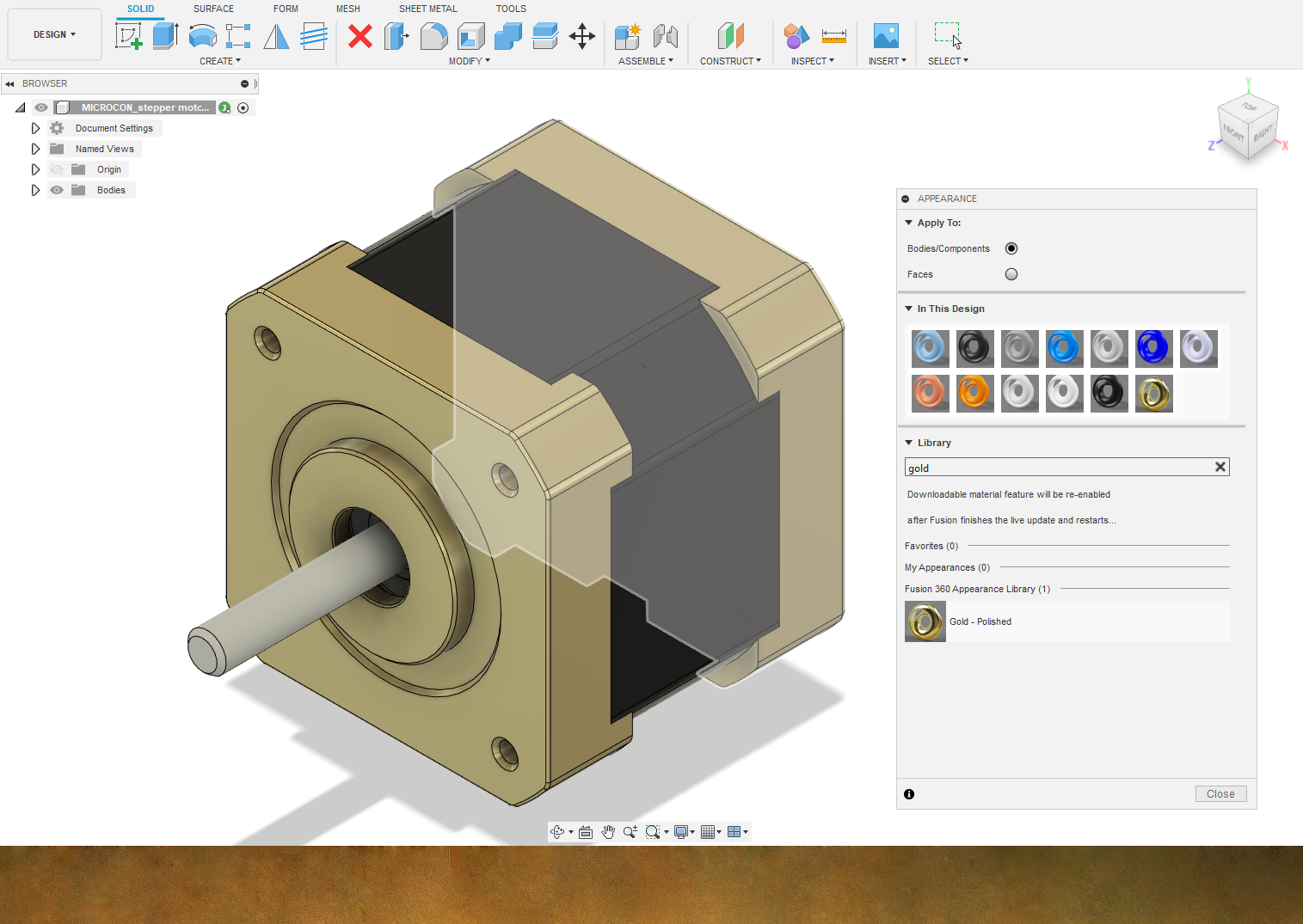
Modifying the appearance of different bodies. This can be done by pressing “a” or through the menu below. It’s helpful to see parts as they will appear in real life. If you don’t need “realistic” textures and want to save time to get the same part differentiation effect you can press “Shift” and “n” at the same time to turn on the component color cycling tool.
An important step in reducing the number of revisions in any design involves finding problems as early as possible. Draw parts before they are designed to make sure they are possible to design. While making big CAD assemblies consider putting in the extra work to add all the fasteners so you know there won’t be space conflicts and putting in the fasters gives you time to consider things like whether the fasteners can physically fit in the spaces they are given while assembling the real unit after manufacturing.
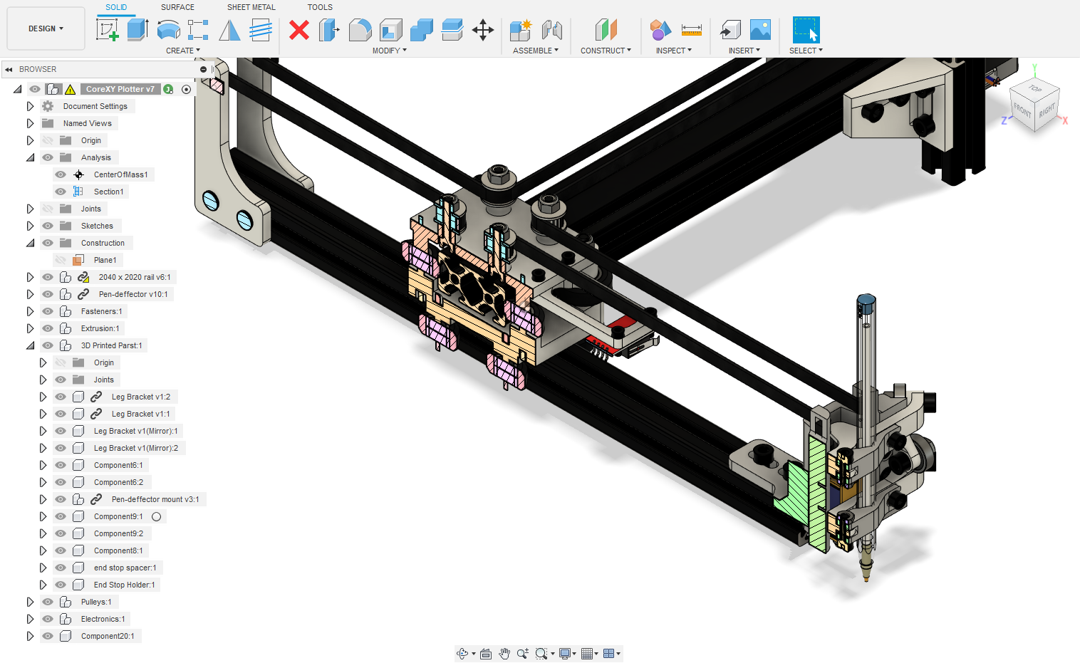
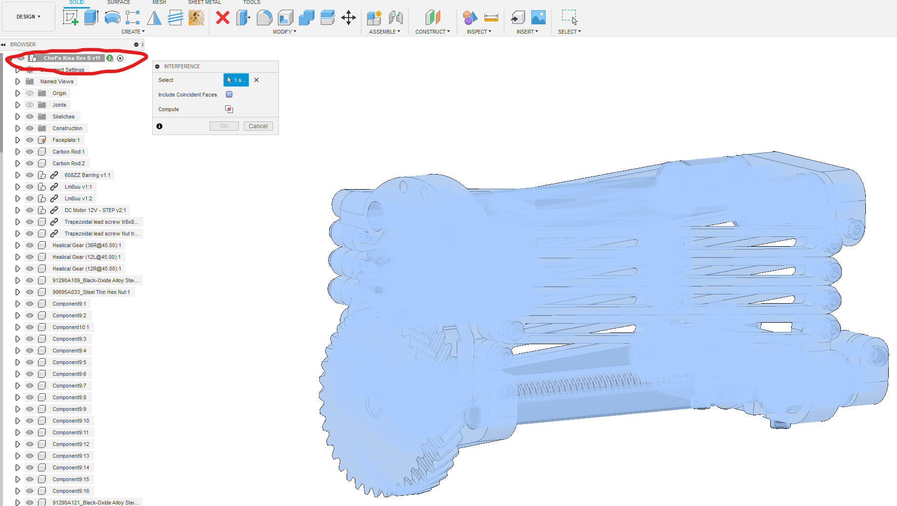
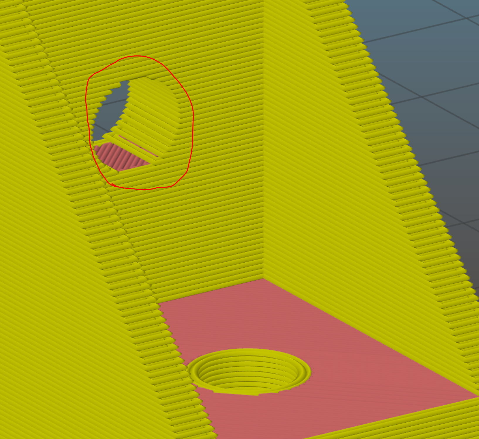
Use the interference tool as a final check before 3D printing or machining the parts in your model. The interference tool makes sure that there are no parts occupying the same space letting you know that there will be problems when you try to assemble the modeled object in real life.

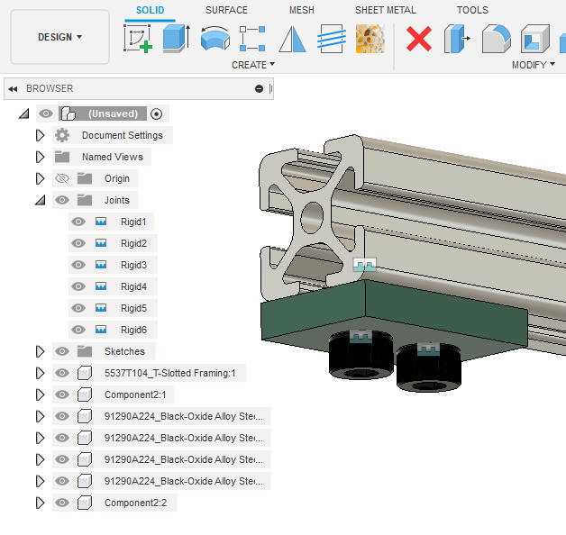
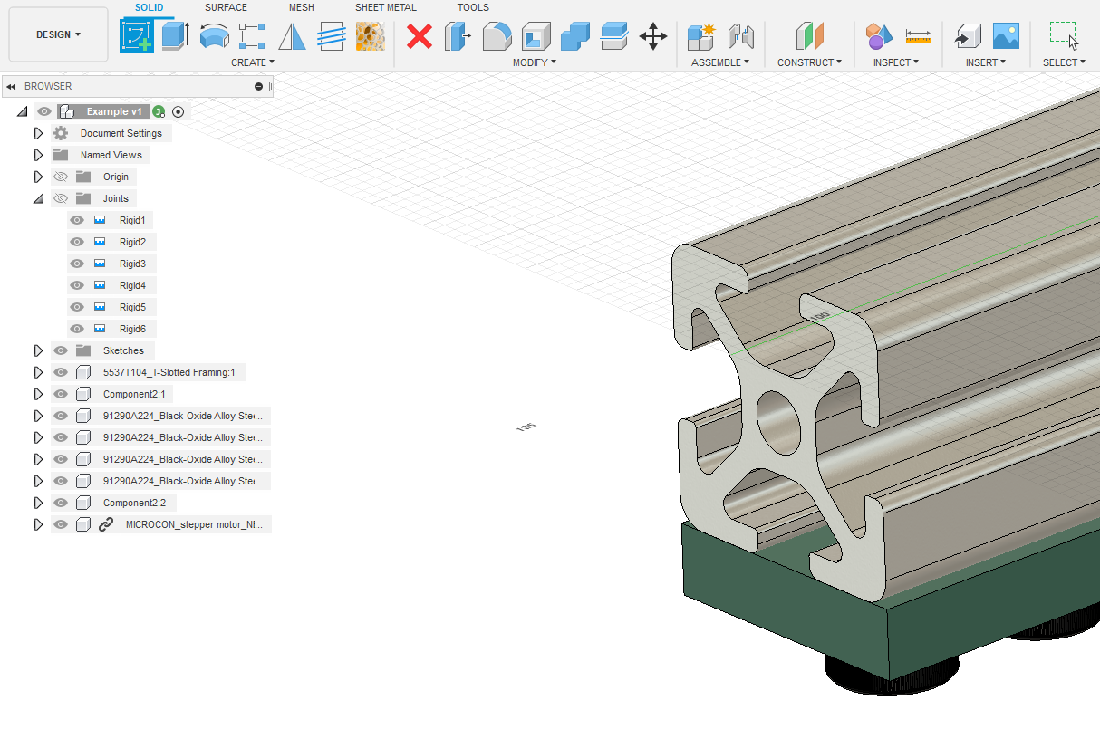
Note that when the Fusion opens the Interference tool it will ask you to select which bodies or parts you want to check interference between. I prefer to check interference across the entire model which can be done quickly by selecting the entire assembly. The assembly is shown circled in red below.
4. Taking it Further and Developing something for this class
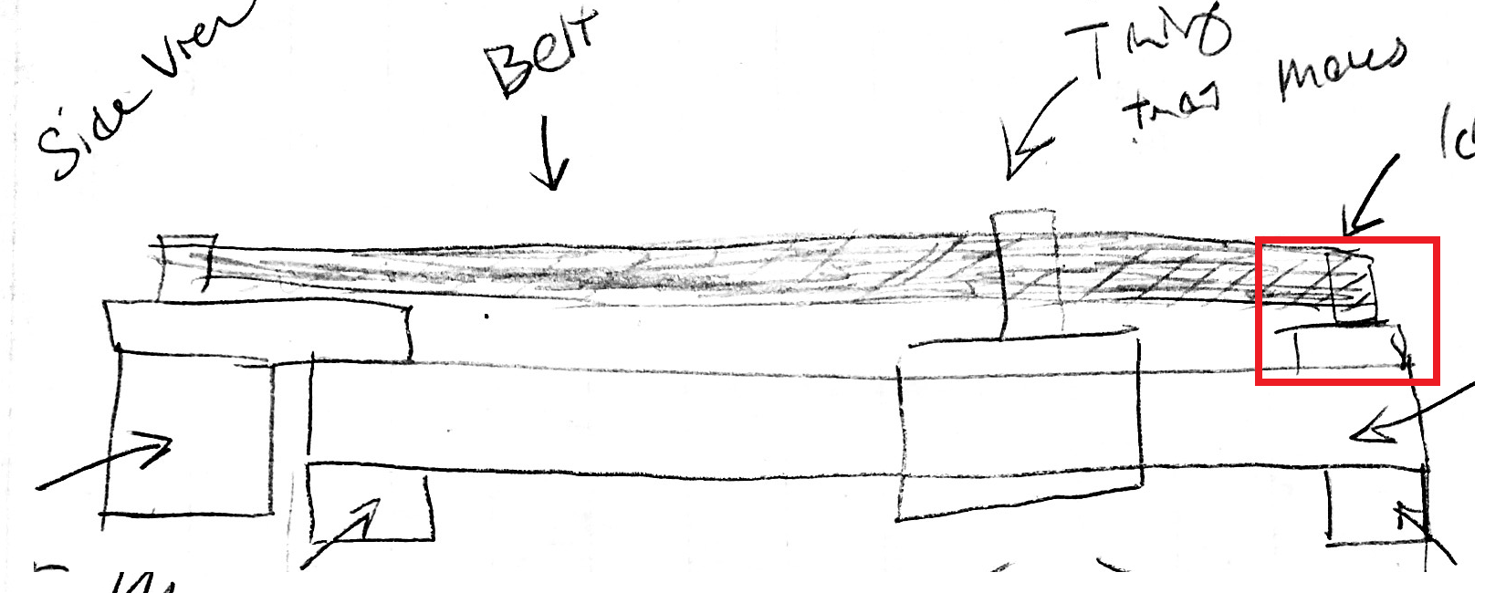
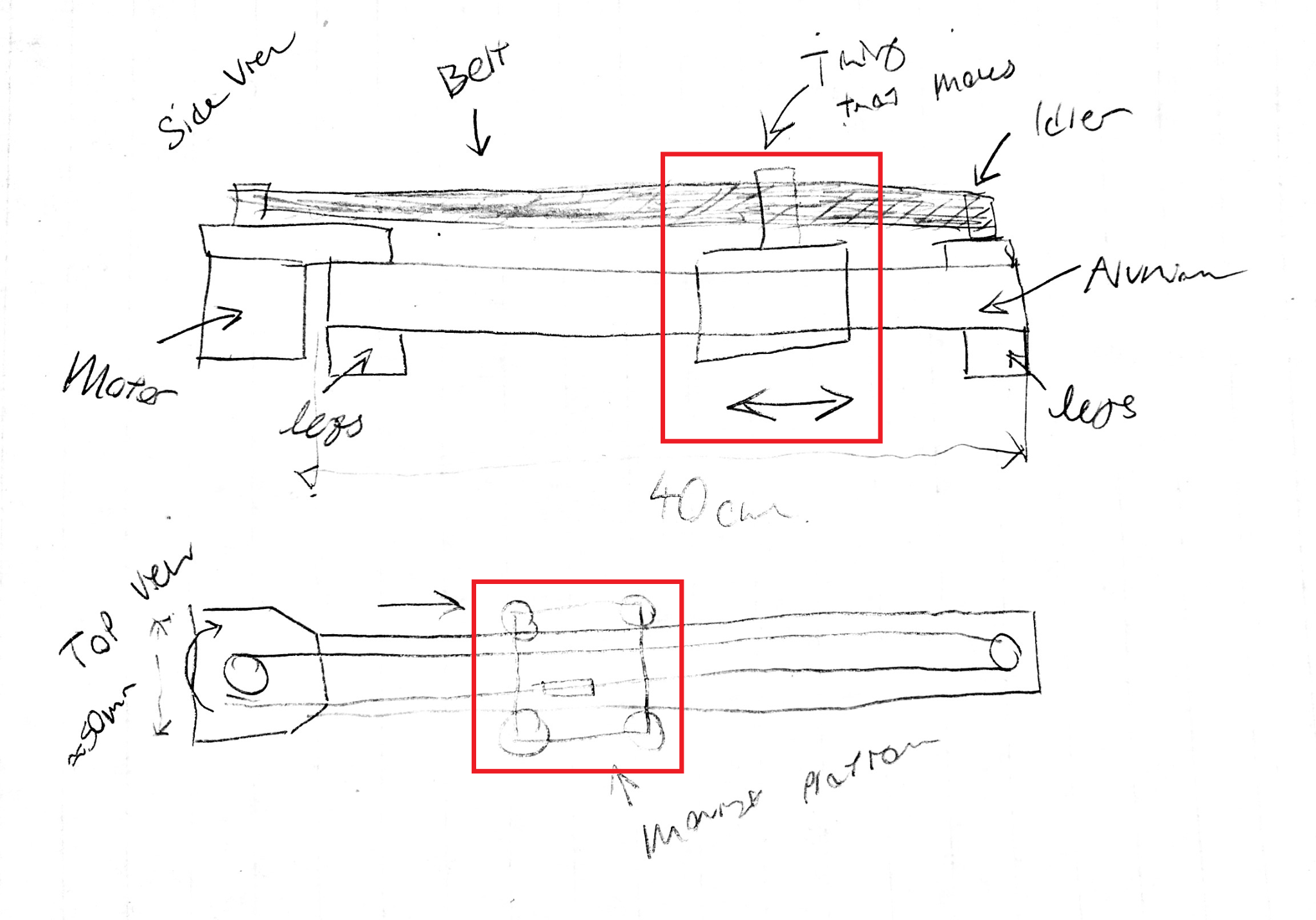
The real deliverable for this class is to make a simple assembly that would function as a driven axis on a CNC system. To do this we will require a small handful of basic parts. There will be a physical frame composed of a base board, a bearing or screw support, and a motor mount. There will be a motor and a moving platform. We will work together to develop it all. Let’s start with deciding on a useful length. I’m going to arbitrarily pick about 40cm long based on my desk. Now let’s grab our base from McMaster-Carr. Throughout this section we will need to acquire new parts for the assembly either by assembling them from drawings or finding them through online resources. Before we get started let’s follow the golden rule: make a drawing of what we’re trying to model so we don’t get lost. The drawing doesn’t need to be perfect but it should make sure that we understand what we’re trying to build and where to start.
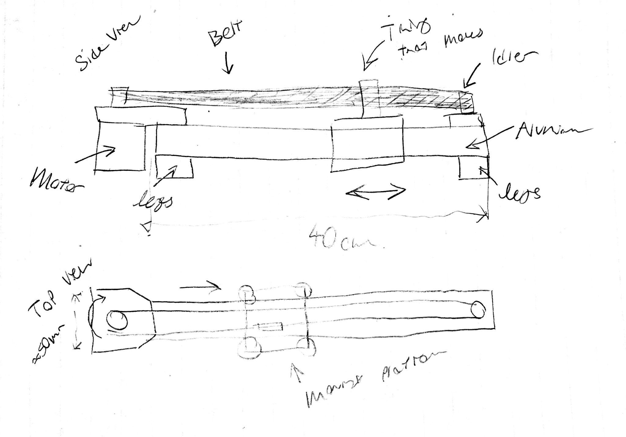
That central rectangle in the drawing above is really a piece of aluminum extrusion. So let’s start there and with the “legs” or the little risers that hold the unit off the ground. It’s always a good idea to get a central part everything connects to out of the way quickly.
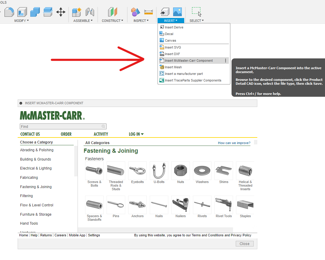
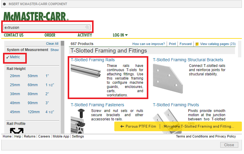
Note you may have to sign in to McMaster-Carr to download a step once we find the right model. With a McMaster account we can download as many models as we need for free. To get to the part we are looking for we can navigate through the homescreen or just search Extrusion and click on Metric and T-Slot and Framing. Note that there are lots of profile types under the envelope of extrusion. For our design exercise we don’t really care about the specific profile geometry but if you are building something like this for real ensure you are buying V-groove stock as bearings will run much smoother in it.
Next find this generic 20mm single profile in the 2ft length and select 3-D STEP and download. This will automatically add the part to your Fusion 360 File.
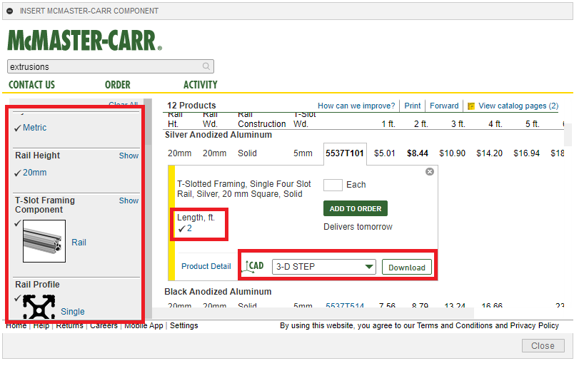
Let’s learn how to use the measuring tool to make sure our part is 2ft long and to see how much we need to shrink it to use it in our assembly.
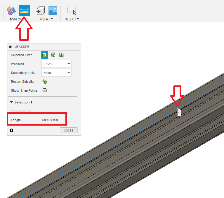
The measure tool is very versatile. Here I have clicked on an edge of the extrusion. The measure tool assumes this edge is a line and returns the length of the line in the red box above. It will also measure the distance between multiple distinct points or faces. In this case, clicking the line is the fastest part.
Now we want to extrude the end of the aluminum so that it matches our requirements. The equation I used to calculate that value is shown below.
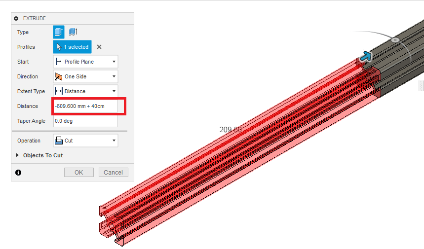
You can measure the extrusion again to see that it is the correct length now. This process is remarkably similar to the way we would need to cut down the material during the real world assembly. Let’s grab a flat face on the bottom of the extrusion to make the foot to hold the bar off the ground from the drawing (face highlighted using a lighter gray).
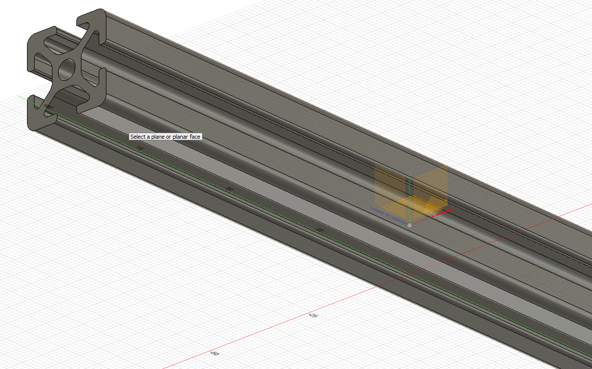
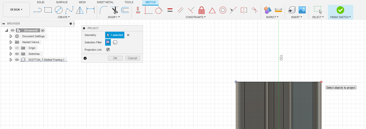
You can press “p” to bring up the project geometry tool which allows you to turn physical features and even parts of other sketches into your sketch as lines or arcs to use. Simply click on something and voilà it is now a piece of geometry you can use in this sketch. Now we’re officially moving onto making new parts. Let’s start with a small one: the Legs from the original sketch. Highlighted in red for your convenience.
If you want to see my final version before starting, here it is:
Grab those two points on the end of the extrusion so we can set a box equal to that length. The rectangle tool is inside the create menu and grabbing the 2-point option allows us to make a rectangle and plop it into that corner so that corner is locked in.
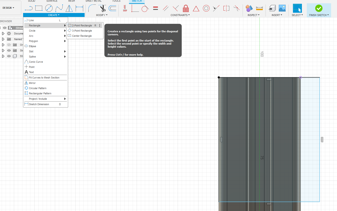
It should look something like this. Next we need to start using the sketch constraints. They are the red and grey tools called constraints. All of them are very useful. It would be worth your time to familiarize yourself with them, but for now let’s focus on the collinear tool.
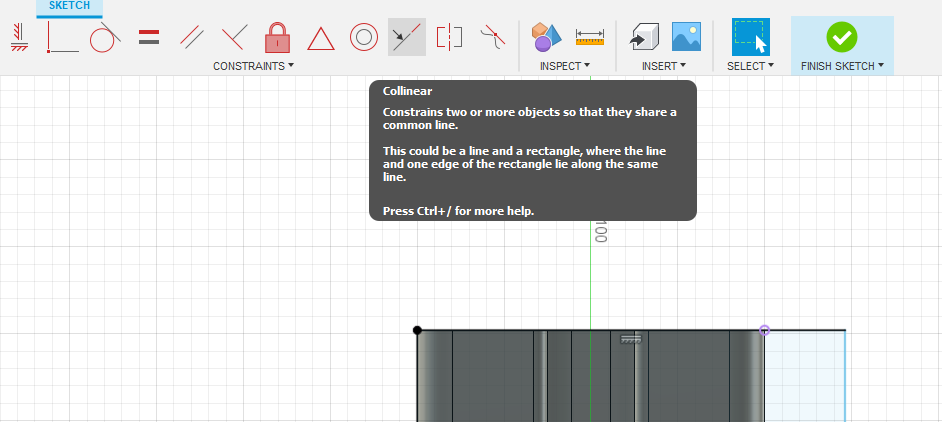
Selecting this tool allows you to make two lines coincident.
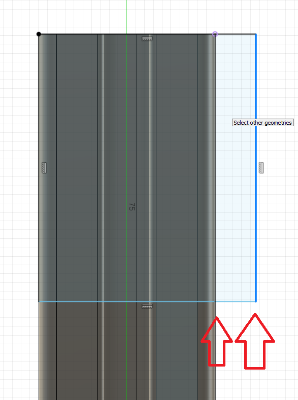
Click these two lines to lock the other edge of the rectangle to the extrusion. You may notice that the more we work, the less blue in the sketch. Blue lines are lines that are “unconstrained” or that move when you drag them. It is often a good idea to remove all blue from every sketch everytime. For the last blue line left in the sketch we need to add a “dimension” or specified length. This tool can be used by hitting the “d” key or in the create menu. Click the side of the rectangle running from the top to the bottom and click again to look in the dimension. Double clicking on the dimension allows you to edit it.
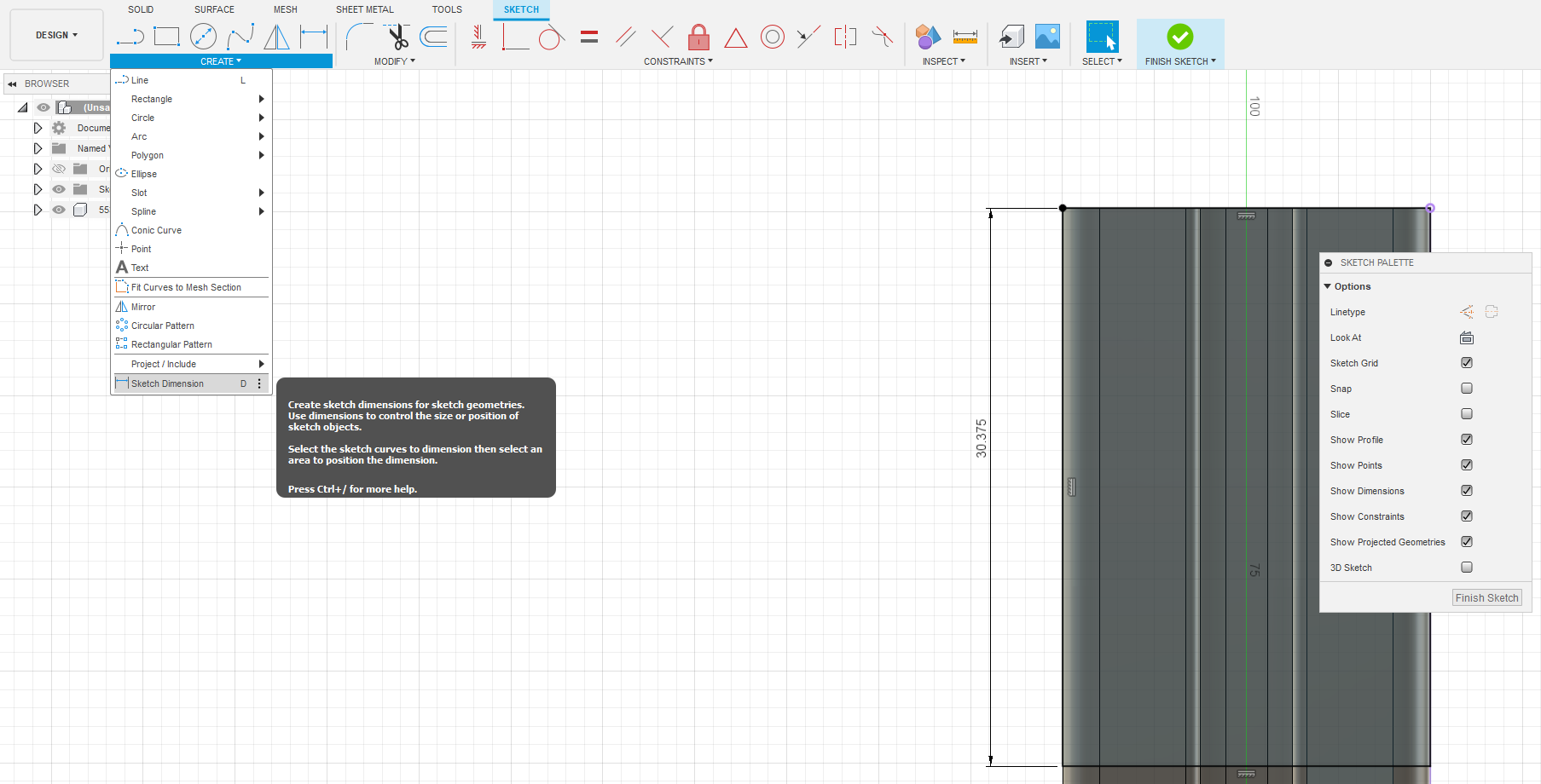
Next use the “point” tool to create a center point at the top. We’ll use this to make a centerline for the mounting holes for the foot.
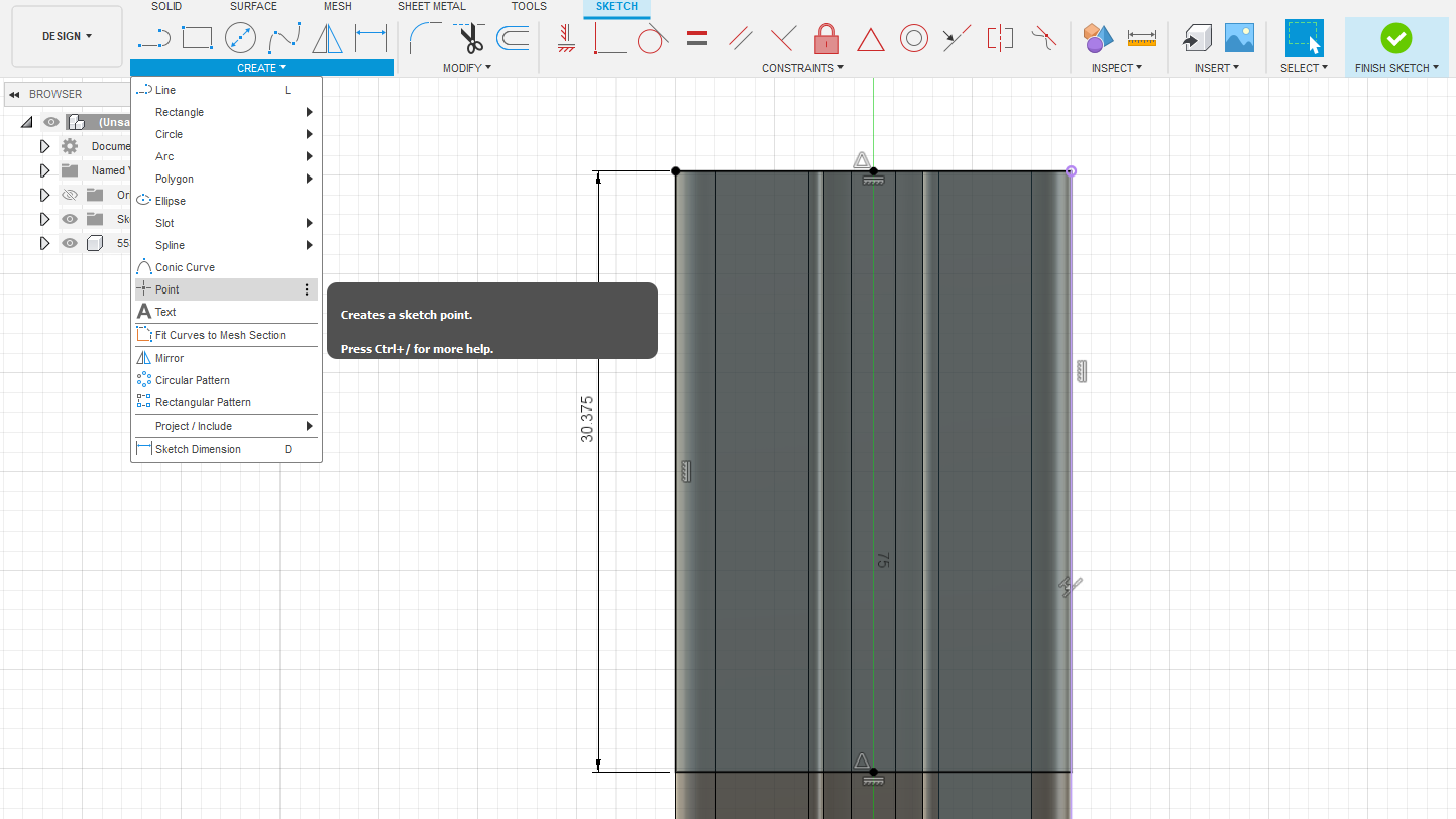
Sometimes it’s nice to make lines in our sketch that the cad software won’t want to make features out of. This is called construction geometry and it will be clear why it’s useful later. Find the highlighted top left square in the sketch palette or hit “x” to activate construction geometry. Make a line from the point we made in the middle of the top to the bottom. Ignore the curvy left line in your drawing, it’s just to demonstrate that construction geometry is dashed not solid lines. Press “x” again to make sure it’s disabled for the next step.
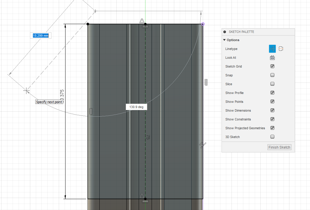
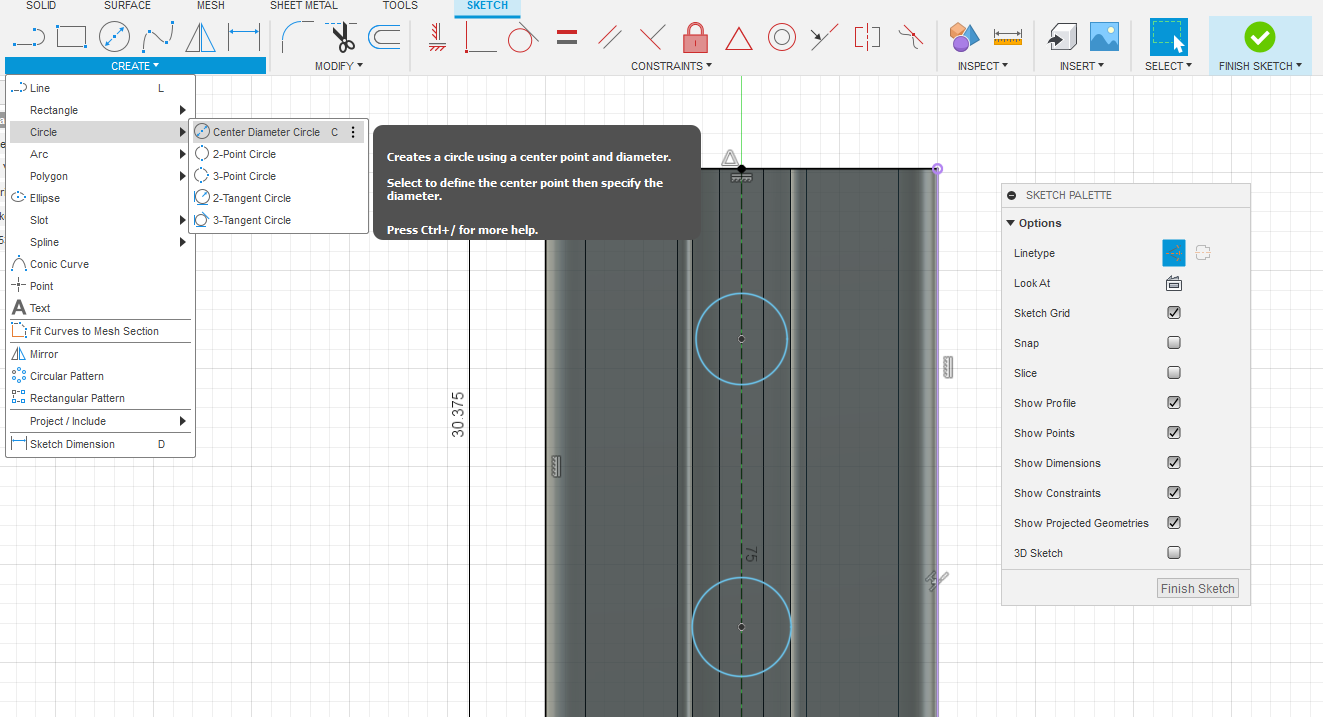
Make two circles. Ensure their center points are on the line when placing them. The exact radius doesn’t matter yet.
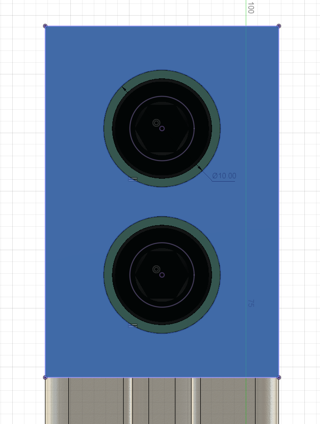
A cool way to center objects when we only care how far they are from each other is the following equation. When editing dimensions, Fusion doesn’t care about units or even if you want to use math to calculate the final answer (like Excel). Here we are using “d3” and “d4” which are dimensions 3 and 4. You can add these to a dimension by clicking on them once while editing another. This equation is really saying (30.375-15.000)/2 so we can change the individual dimension of the part but the holes will always autocenter. If this relationship doesn’t make sense check this out
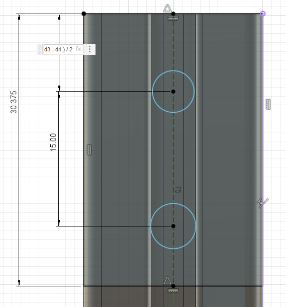
Now the real advantage of taking this time to make it work well comes into play. We can change those random filler values from before as much as we want and the holes will stay centered relative to their middle point. 30.375 is less nice a max size than 30mm, and 15mm might be a little wide.
We’re almost done with our first part. Just hit the finish sketch in the top right corner.
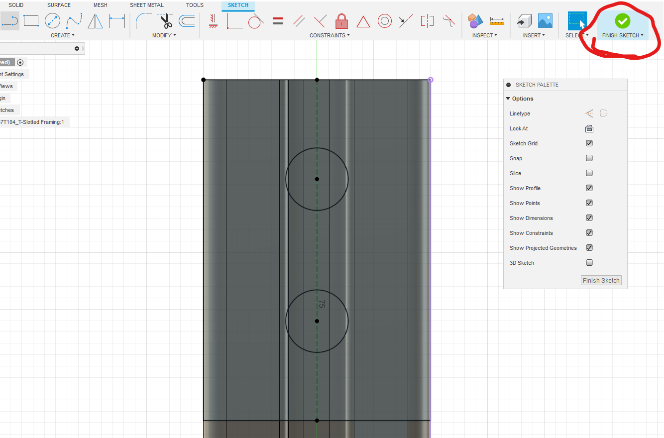
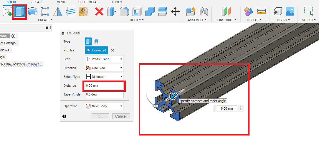
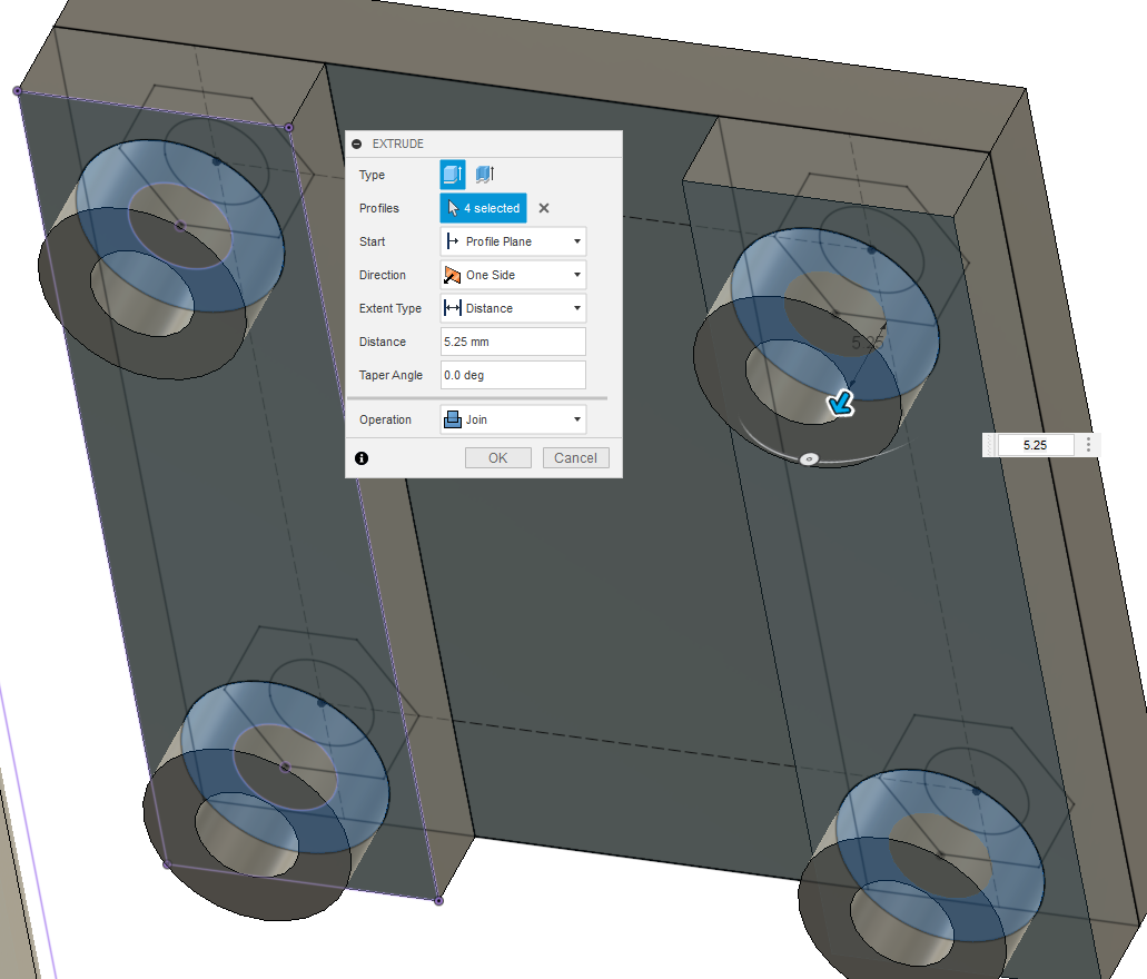
Now hit the important Extrude button in the create menu (the second icon on the top command bar).
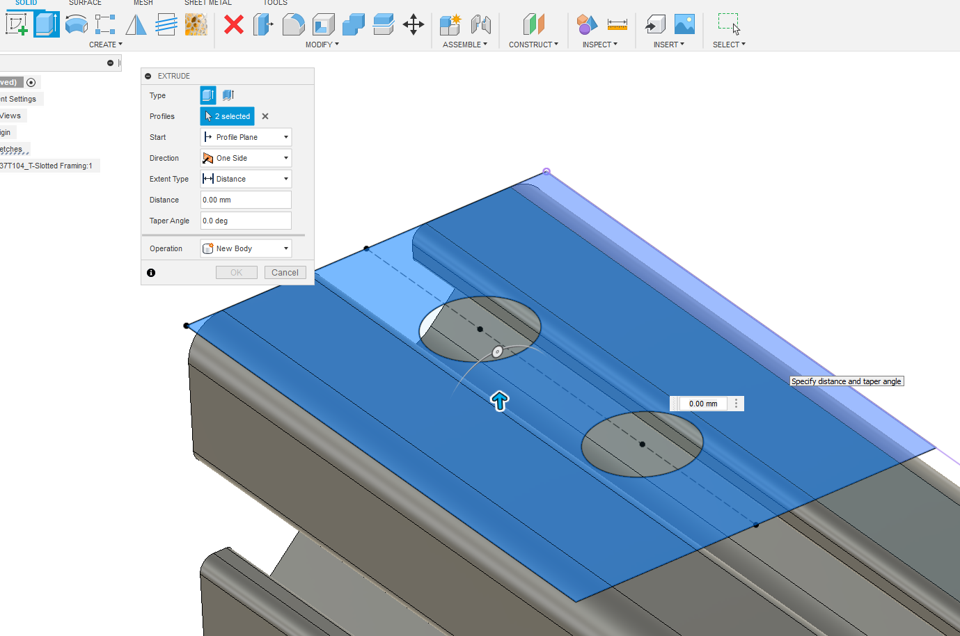
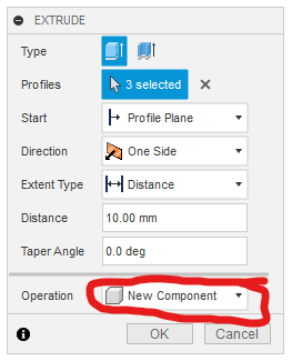
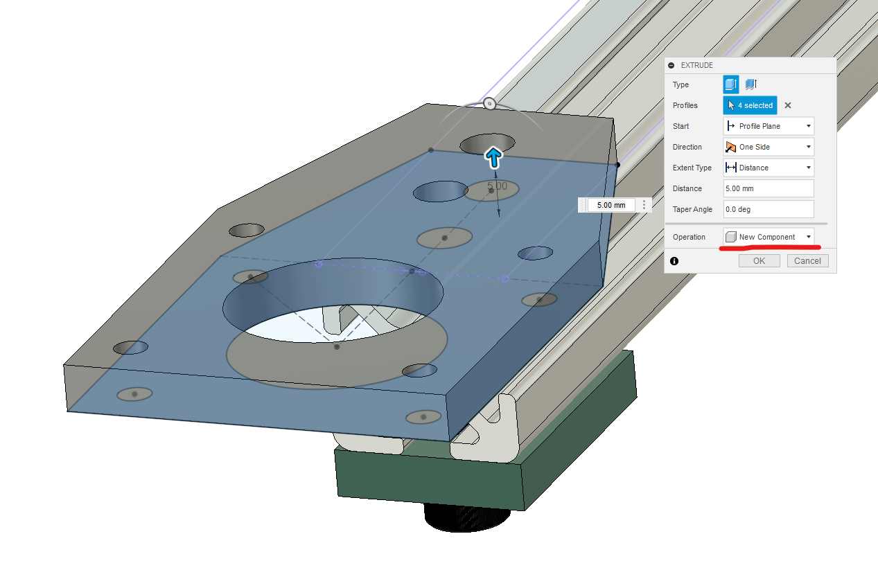
Extrude the part out to 10mm. Make sure that the operation isn’t “join” or we’d be adding to the aluminum extrusion instead of making a separate part. This is important because separate parts can be 3D printed without modification.
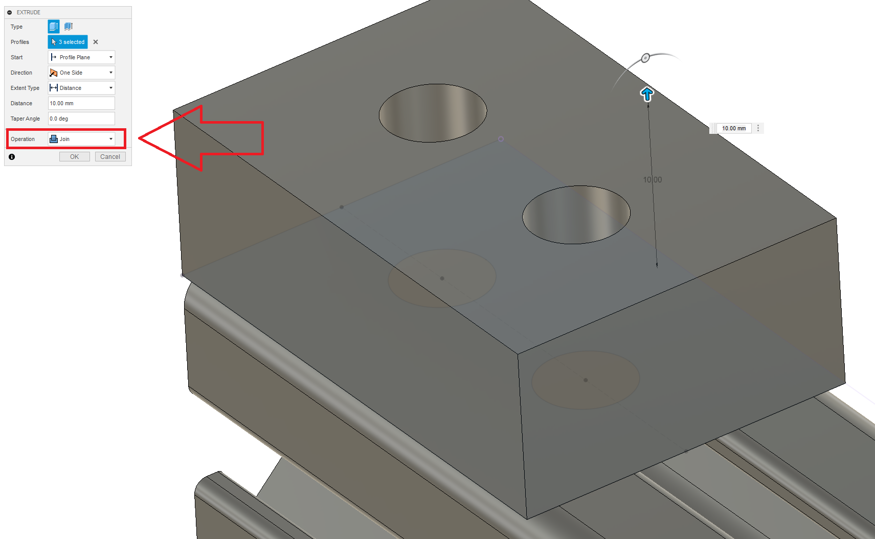
The extrude dialogue box should look exactly like this:
Now that we have a part, let’s add some pretty fillets to the edges. Saves material too. You can fillet by hitting the “f” key or by clicking the fillet button in the modify section.
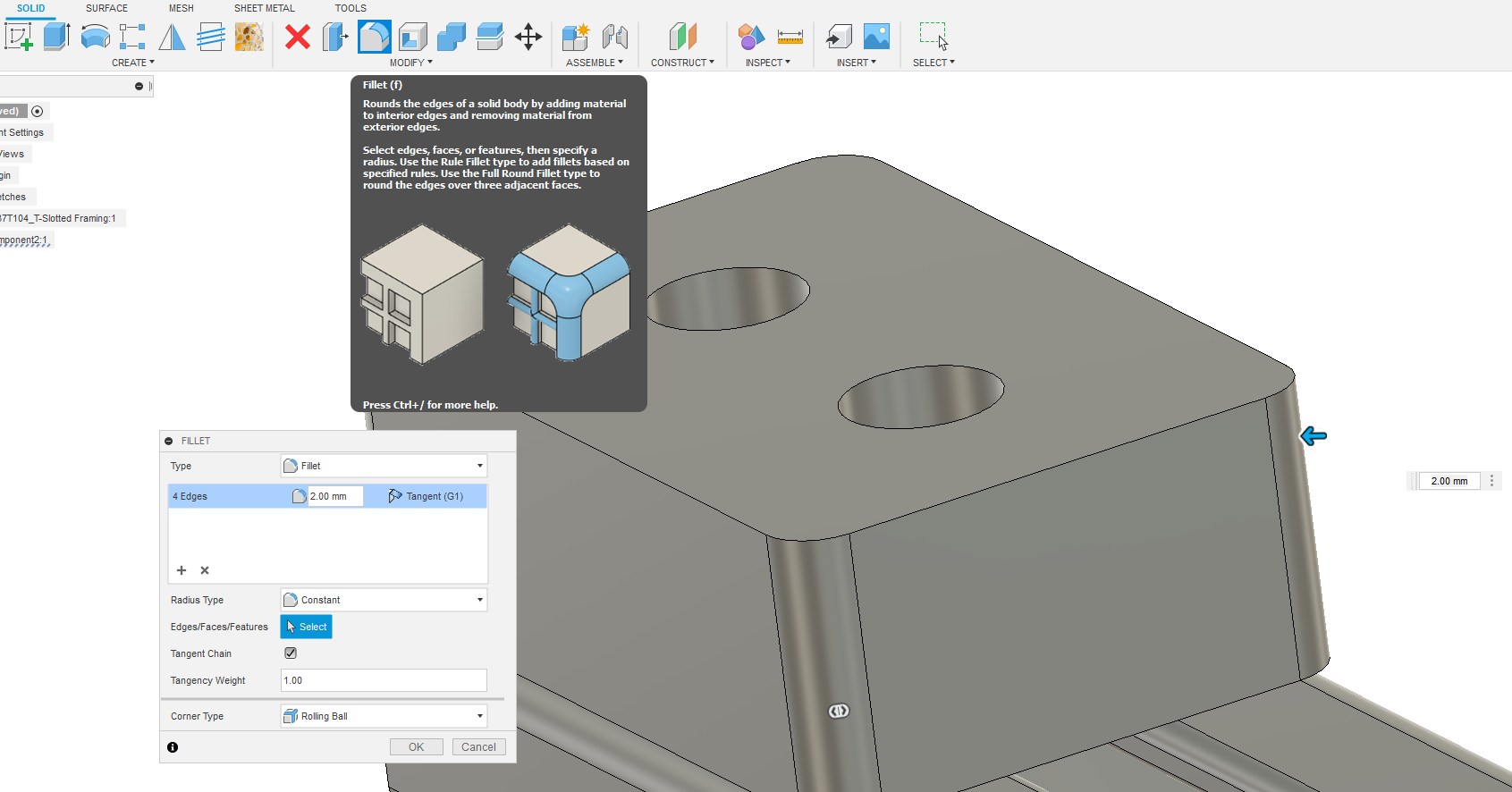
You can decide to undo changes and modify things at any point in Fusion
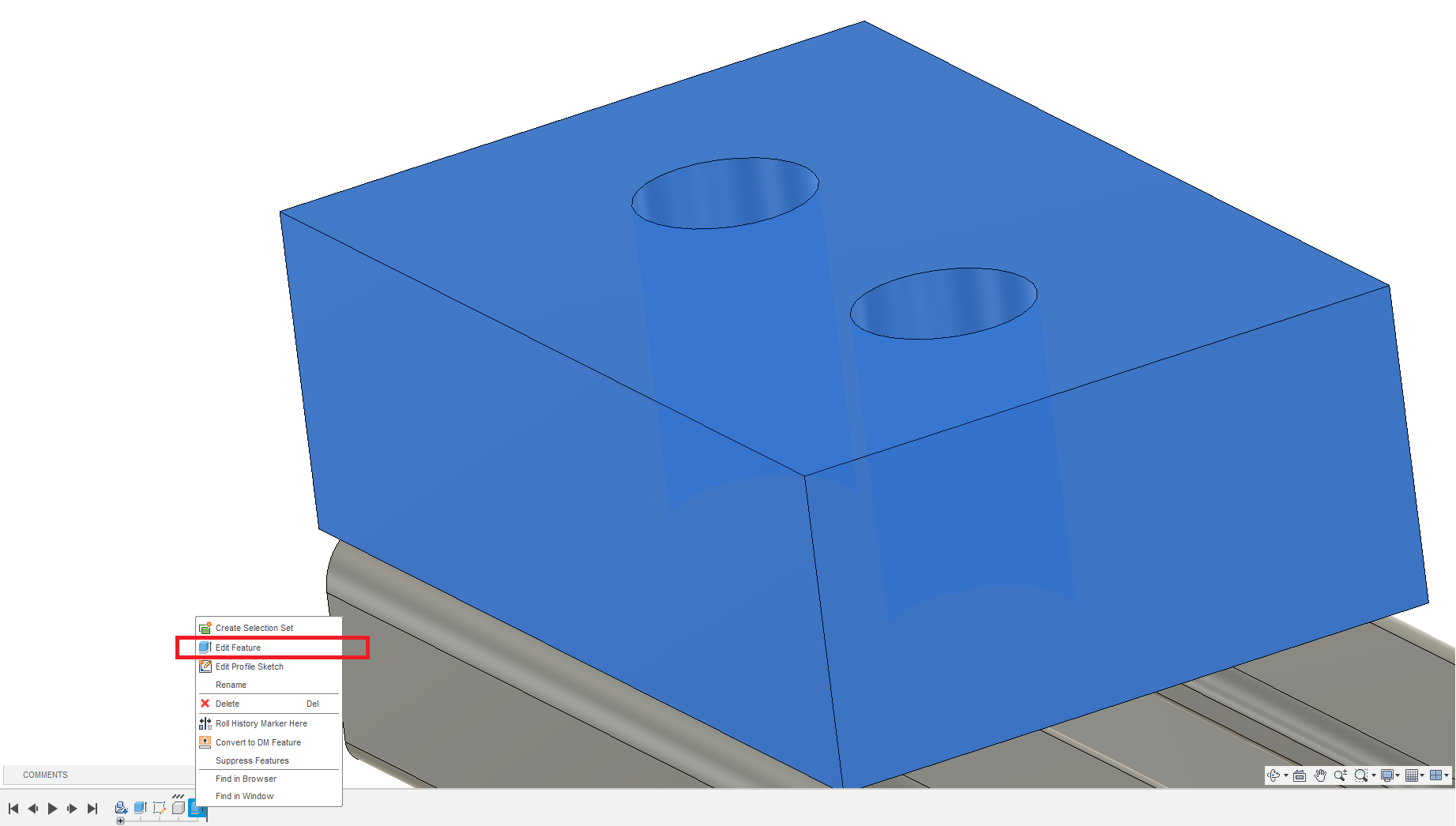
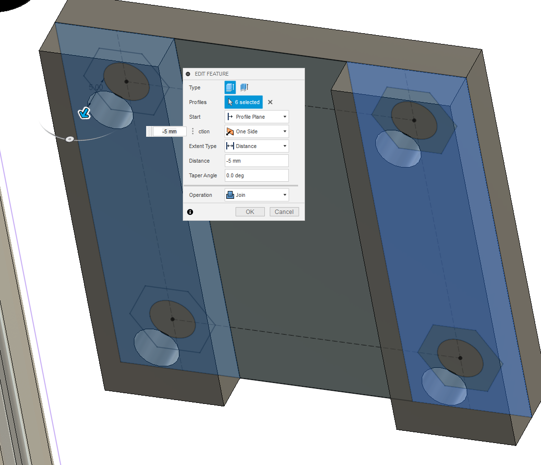
- I decided I didn’t love the way this fillet looked and that I wanted the foot to be smaller. So I used Control Z to undo the fillet, then right clicked on the latest feature on the timeline and clicked on “edit feature”
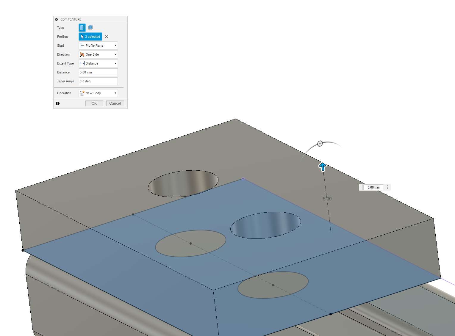
You can now change the extrusion value to anything you want. I’ll go for 5mm.
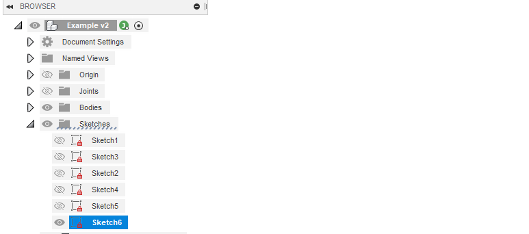
If we want to make changes to the sketch we can use the browser to find the sketch and modify or make it visible again. We can also use the timeline for this.

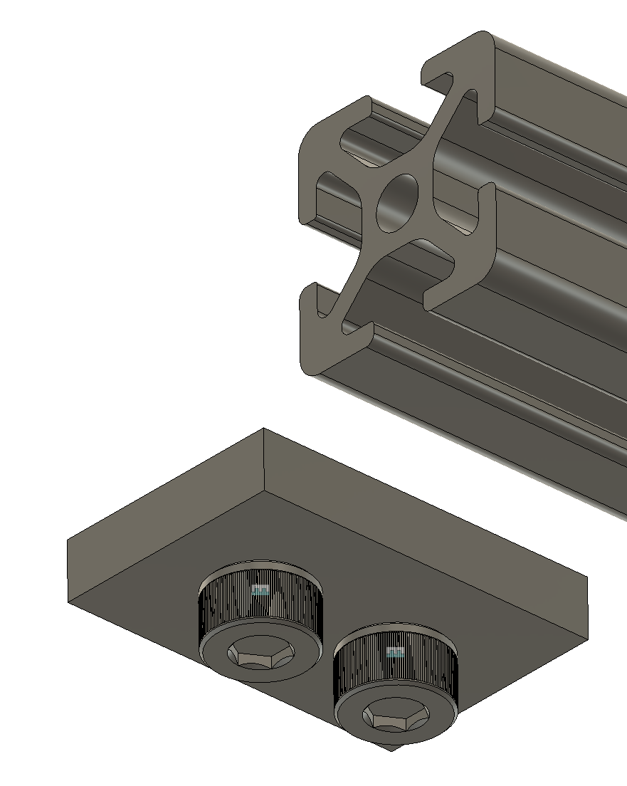
We now have a part we can 3D print to attach to the extrusion as a kind of “foot” so it rests off the ground. To secure it in place lets get some bolts. To do this, we need to know how long they need to be before they conflict with the metal so they can tighten any further. This is as simple as pulling out the measure tool again.
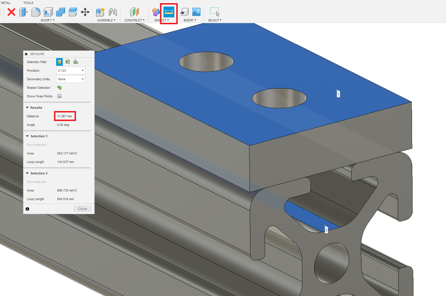
Based on the measure tool and the 20mm extrusion profile we are using we can tell we need an M5 screw that is shorter than 11mm. Let’s see what McMaster has.
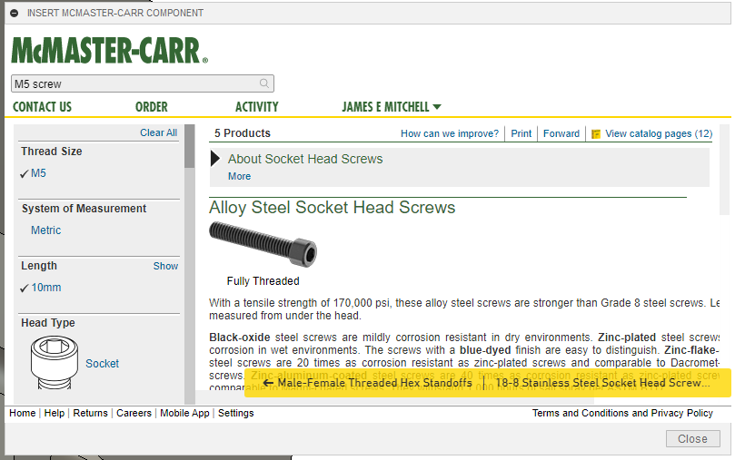
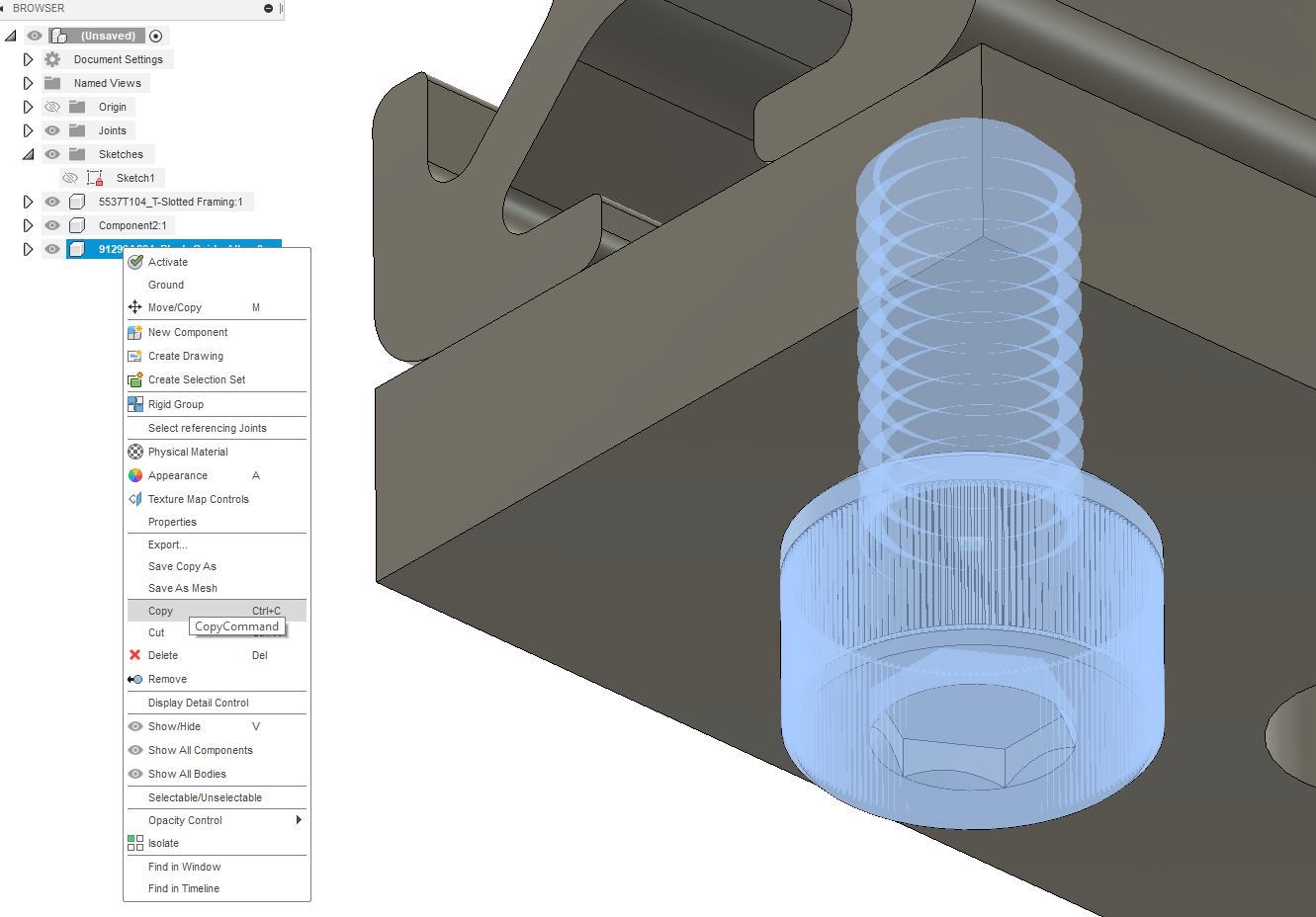
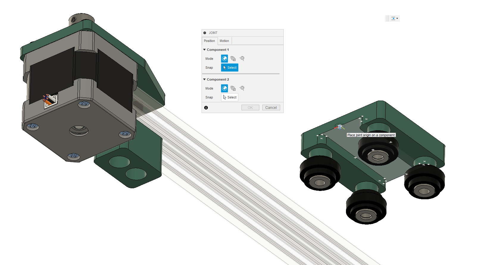
These look perfect. Let’s get the STEP file for them to add them into our design. You can drag components around by clicking and dragging or by using the move tool with the letter m. When we first place a new part in a file, the move tool will be automatically used so we can use the arrows around a part to drag in the corresponding axis. Many parts will appear at the origin which in our case is already being used by the extrusion. Move the screw so that it is outside the extrusion. Now we’re going to use a joint or constraint to stop the part from moving around.
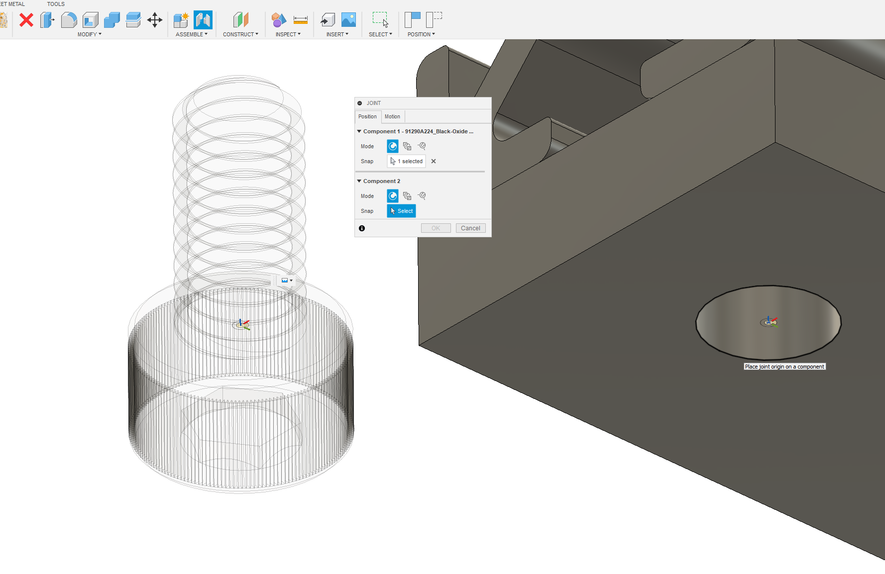
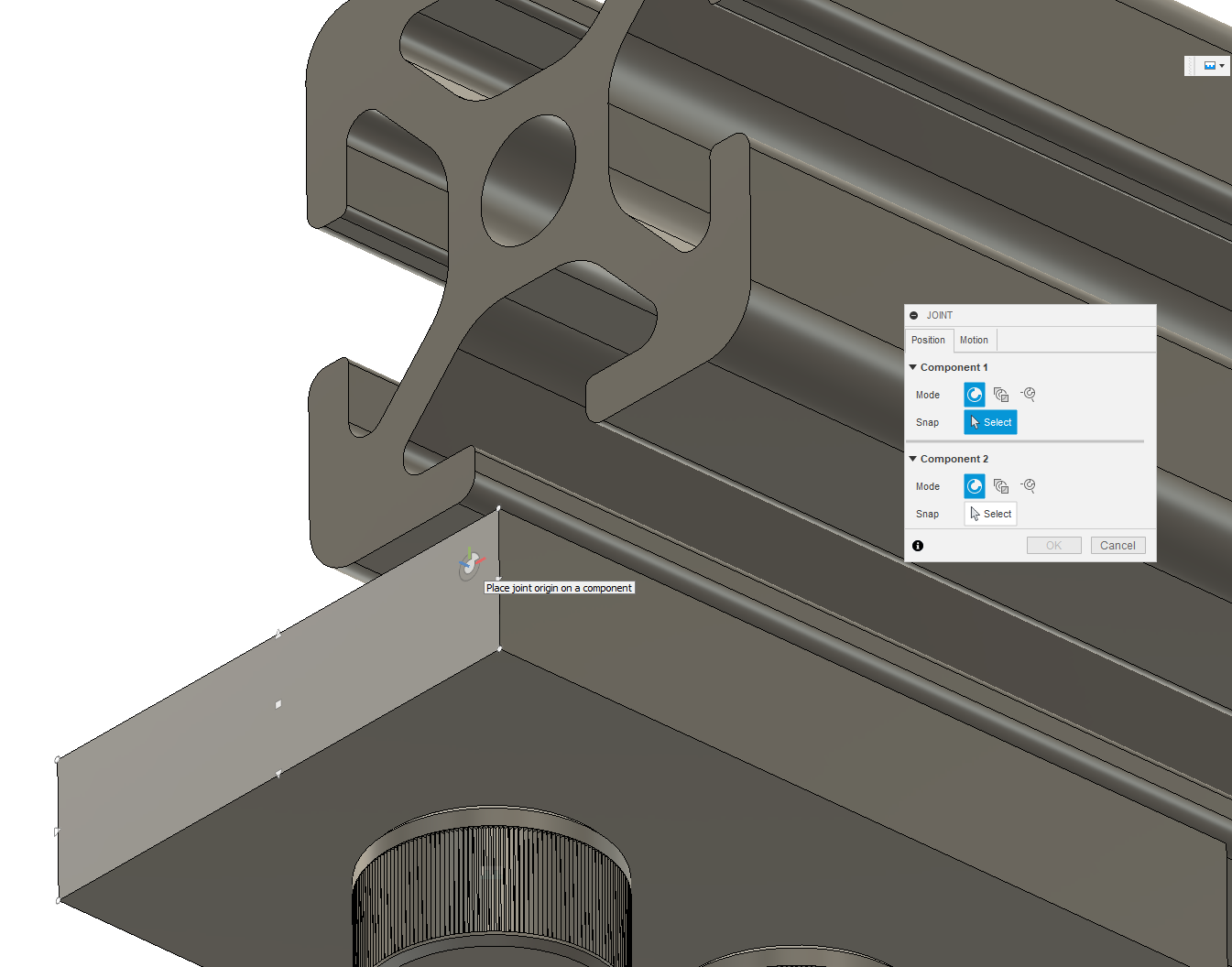
The joint tool can be brought up from the assemble menu and requires grabbing a point on two objects as putting them together. Here we can see the screw is see-through because I have already selected it. This functionality is to make it easier to join things to parts they are already in close proximity.
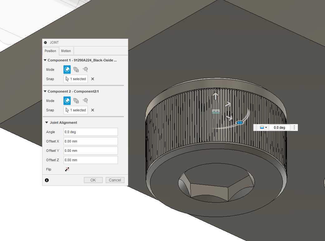
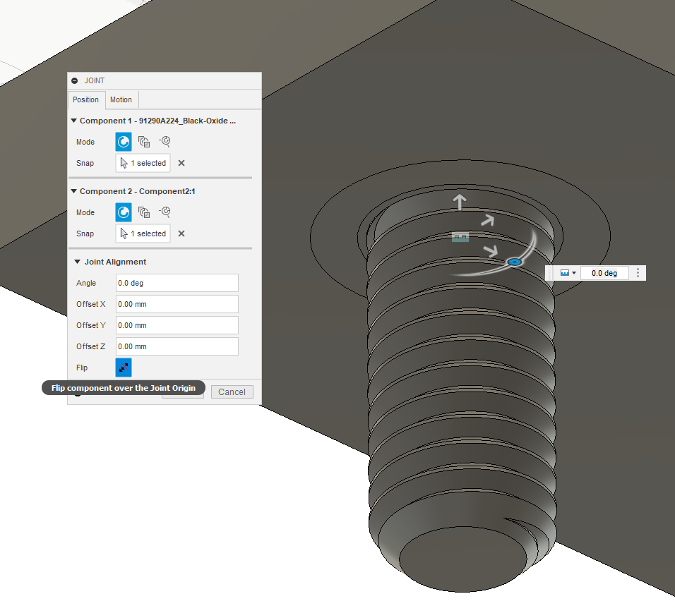
If the part is flipped, use the flip tool to flip it back. The screw should now be in place but we’ll need a second one to finish this foot mount off. This can easily be done by copying and pasting the screw.
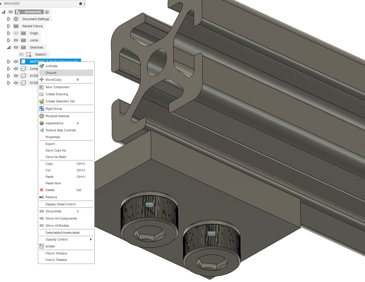
With the second bolt pasted, I simply constrained it to the other hole. Now that those screws are firmly in place, how do I stop everything else from moving?
We are simply going to ground the top piece of metal which will stop it from being able to move relative to the origin and constrain the plastic rectangle to it.
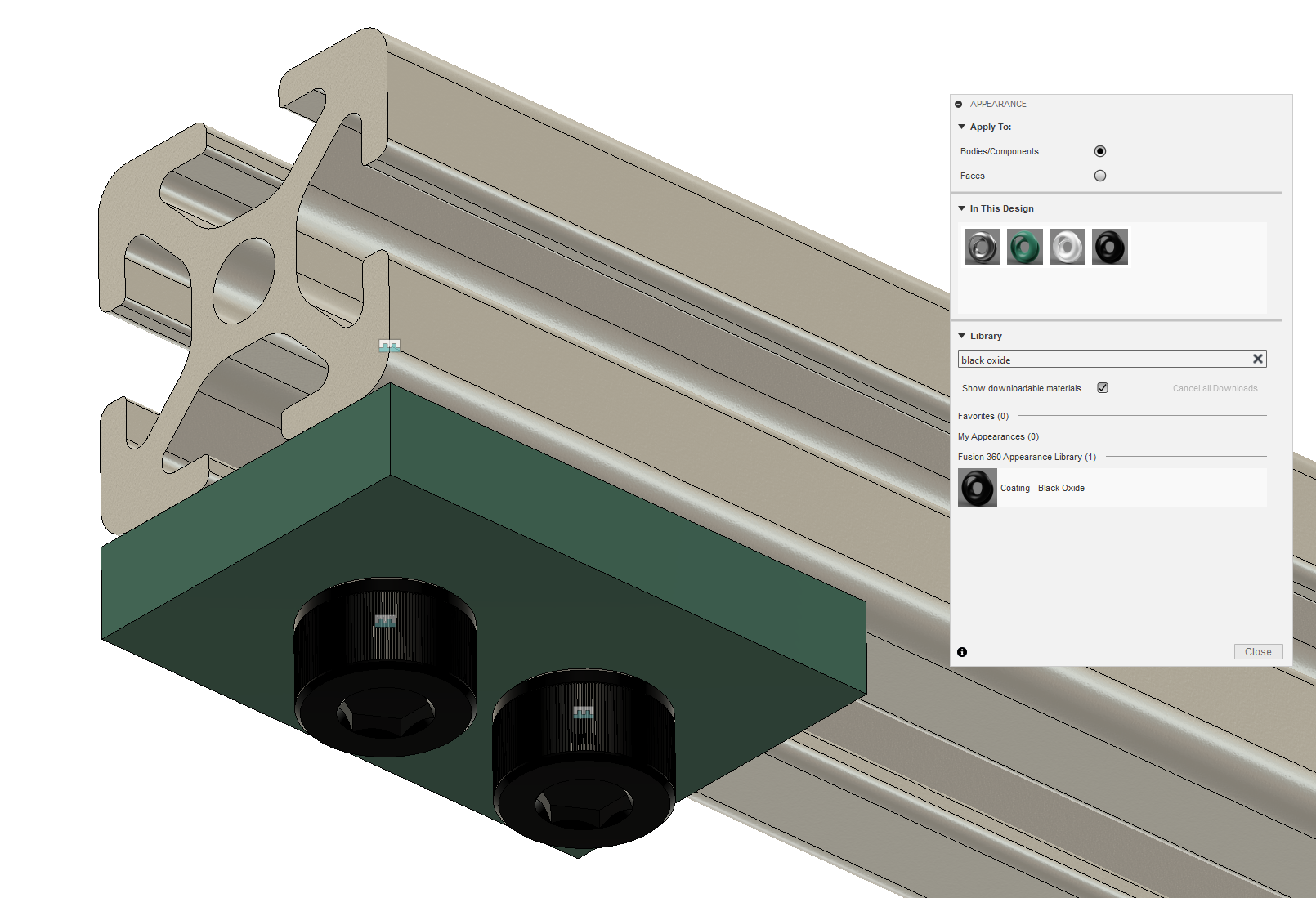
Fusion assumes all parts are a sort of default clean steel texture which makes things ugly and confusing. As we now have four parts in our assembly, I’d recommend taking the time to change the appearances to be more realistic. I pressed “a” to pull up the appearance modifier and I chose a bead-blasted aluminum texture for the extrusion, a teal green plastic for the rectangle, and a black oxide coating for the bolts to match their coating from McMaster. Check out the materials library and feel free to select anything you want.
Now to keep things symmetrical, I’m going to copy the two screws and the rectangle we just made and attach them to the other side.
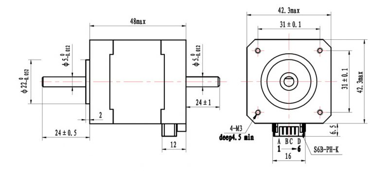
Ah, starting to look like a real product now. Next let’s add the stepper motor we discussed earlier. Here we have another decision. This part we are considering adding to the design is a product that already exists, which means like the extrusion and the screws the model already exists. If you want practice modeling, I have included the drawing below, but we can also source this motor from Grabcad.com or McMaster-Carr. Simply search for a NEMA 17 of the desired length on either of those platforms. I used Grabcad for mine because I liked the textures and appearance of the model more.
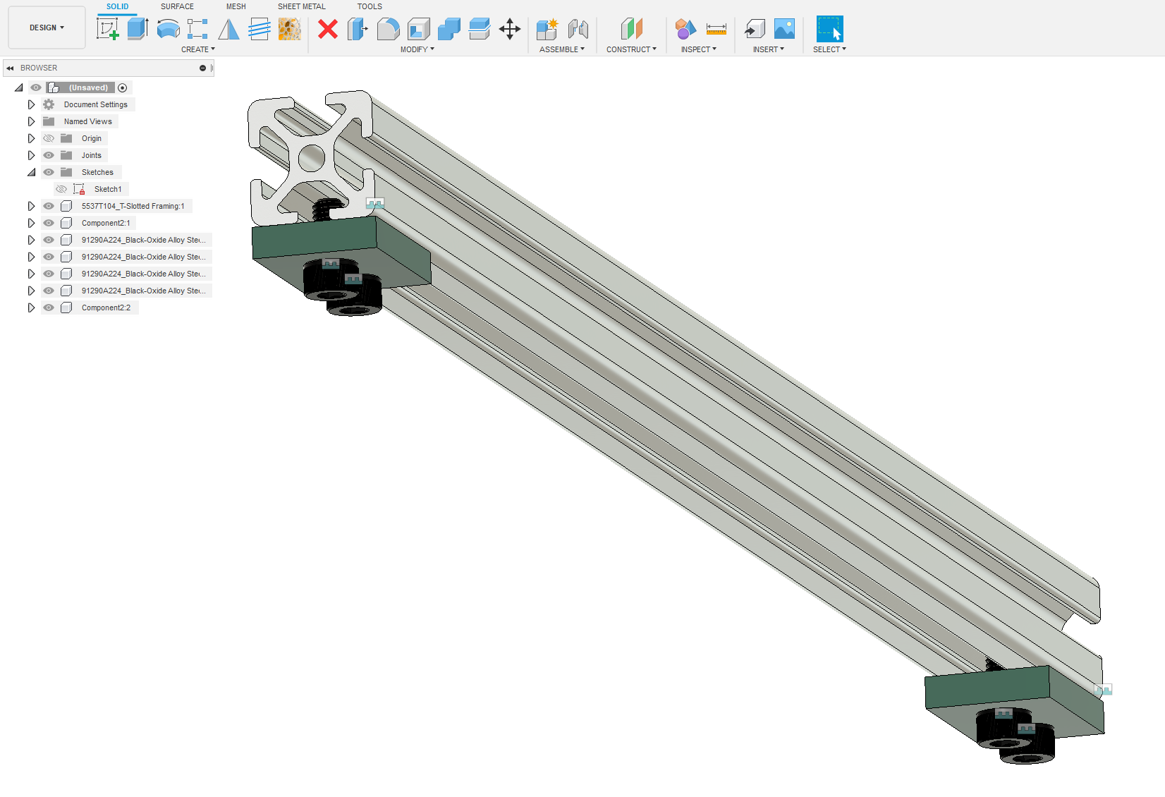
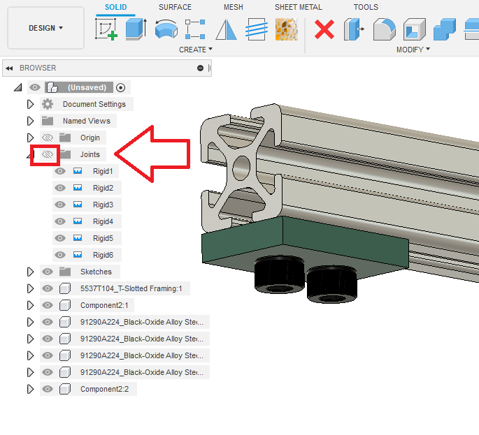
The joints are always visible as small teal and white boxes. If you don’t need to know exactly what’s joined you can turn these off by hitting the joints folder in the browser and pressing v or clicking the eye.
Small difference but worthwhile.
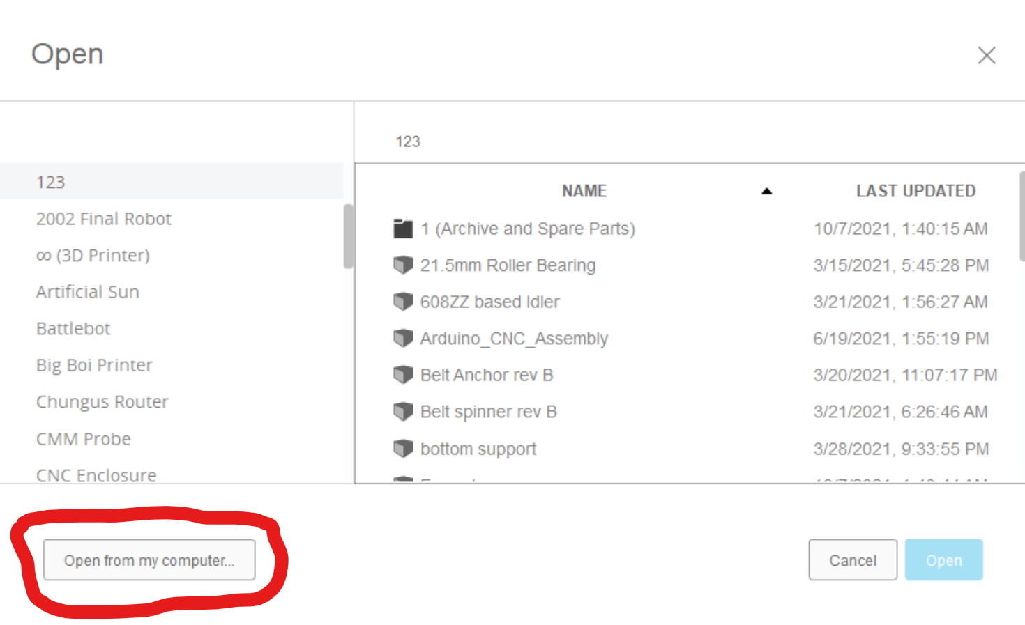
Now let’s get back to that motor. I imported it into fusion. Outside files need to be opened from file > open > open from my computer
It will almost always create the newly opened part on the world origin at (0,0) which means it might be blocked by a bigger part already there. That’s no problem though because any part can be moved easily by selecting it in the browser and pressing “m” to use the move tool.
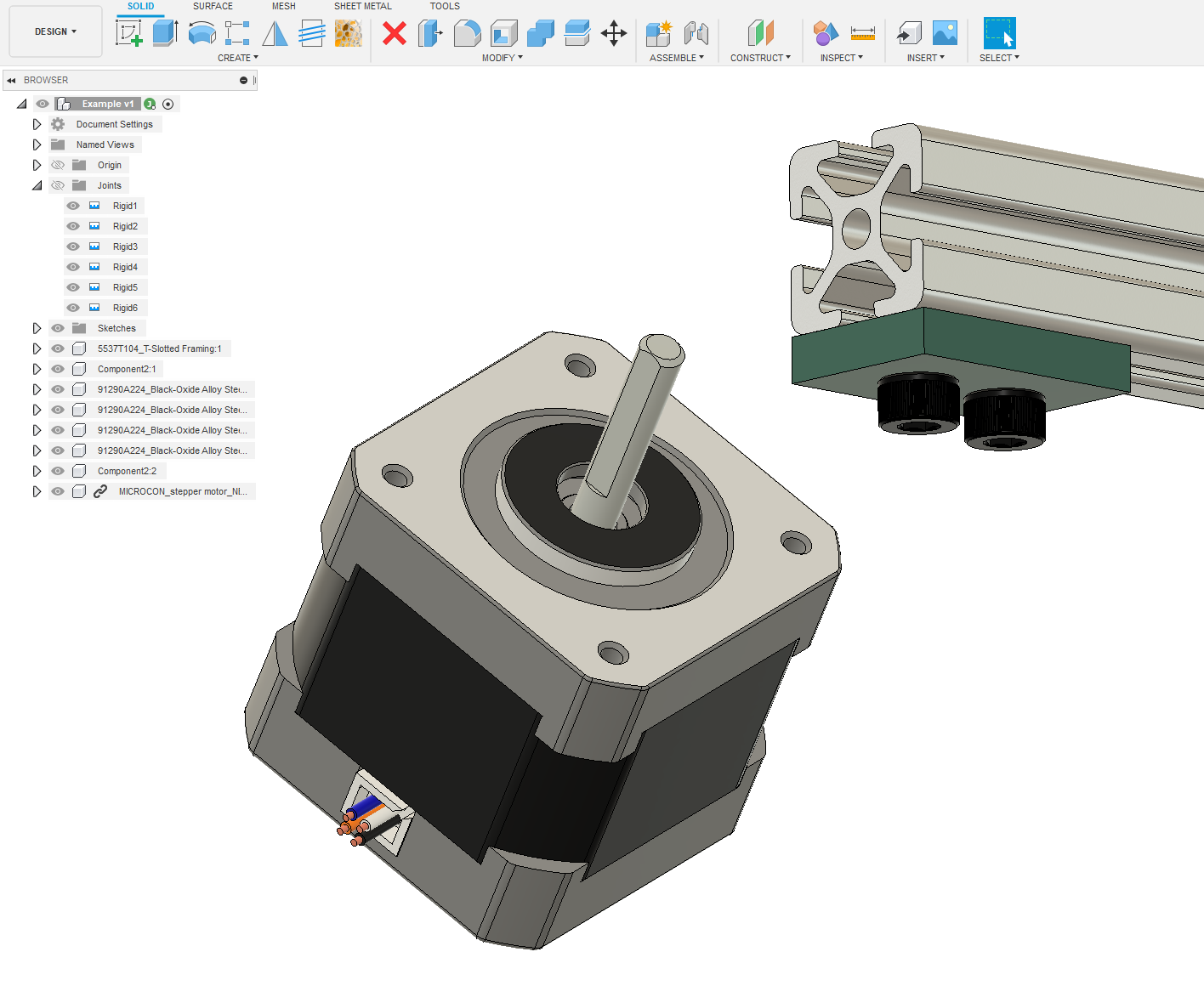
Mmmmm, nice looking motor. Let’s create a sketch on top of the extrusion to start the next part.
Here is my final version:

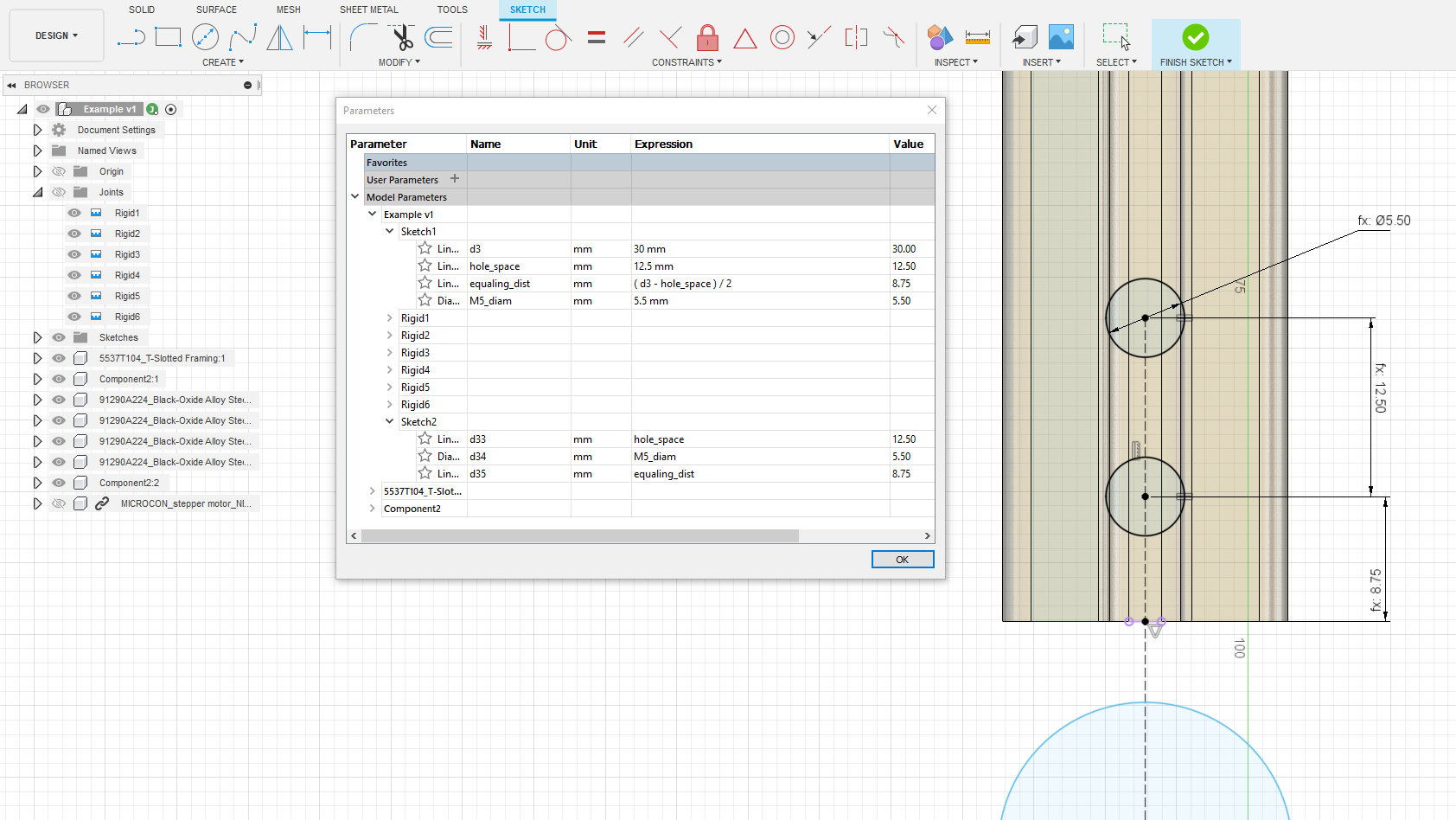
We can start to move a little faster here. Let’s repeat the two hole style design from the last part we made. You can even use those same dimensions to set these distances so you only need to change one number to change this parameter on the whole model. Open the parameters menu by expanding the modify toolset.
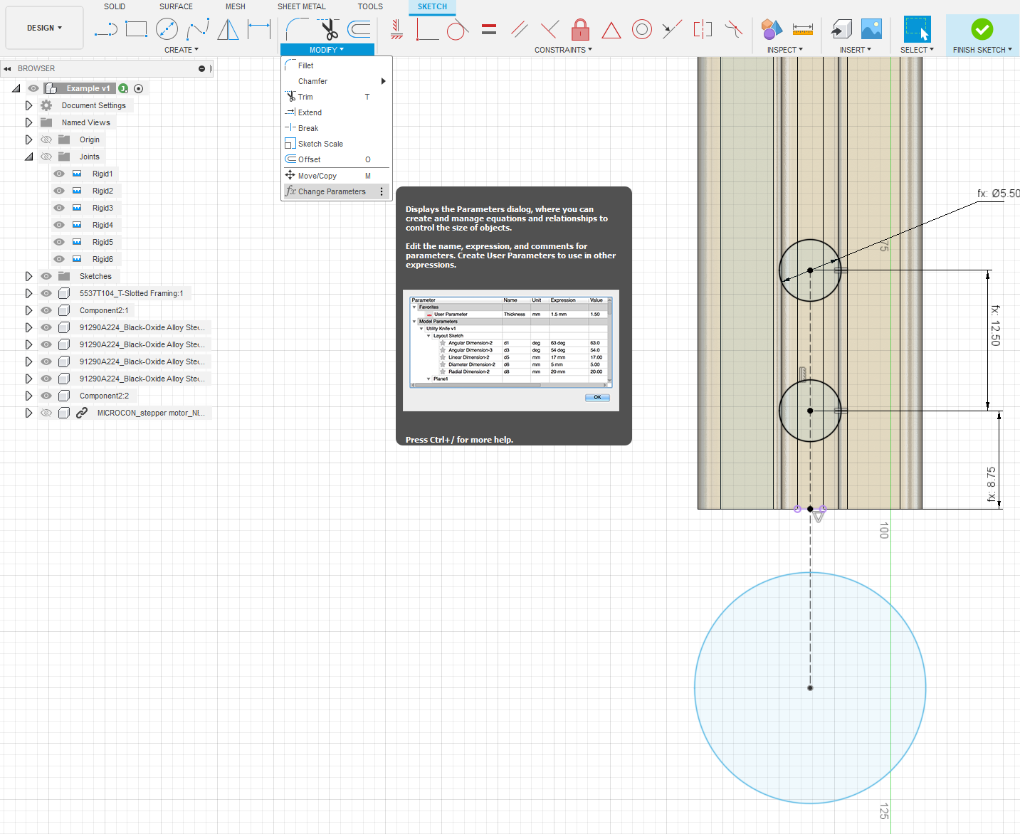
Clicking on it will present you with a spreadsheet that will show you all of the dimensions in the file so far. You can rename them something memorable or keep calling them “d4” or whatever else. Here I have renamed d4, d5, and d6 to more useful phrases and have set them to equal the dimensions in this sketch. If this is still confusing, just set a regular dimension. You’ll have time to look into this later.
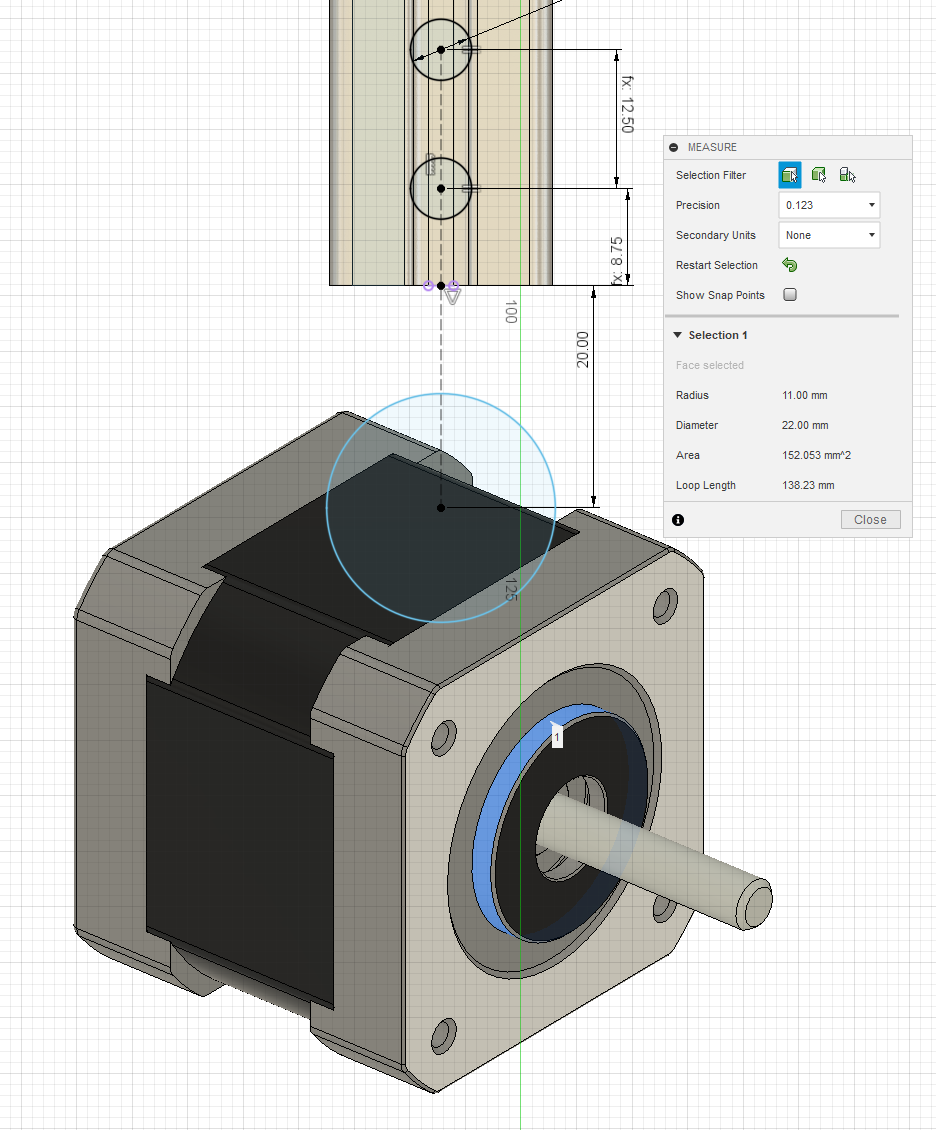
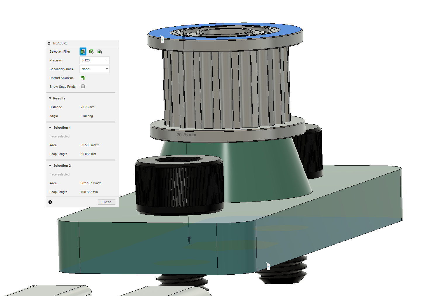
The motor has a big ring that comes up through the middle. I’m not sure how big it is or exactly how wide the motor is in mm, so I’m just going to throw out some numbers here. The diameter of the ring is easy to measure so we can use the measure tool again. Open this with “i”.
Next let’s grab the four face mount holes and add them in. I’m going to use a circular pattern available in the create menu to create the next three.
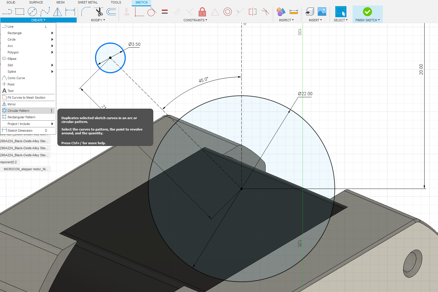
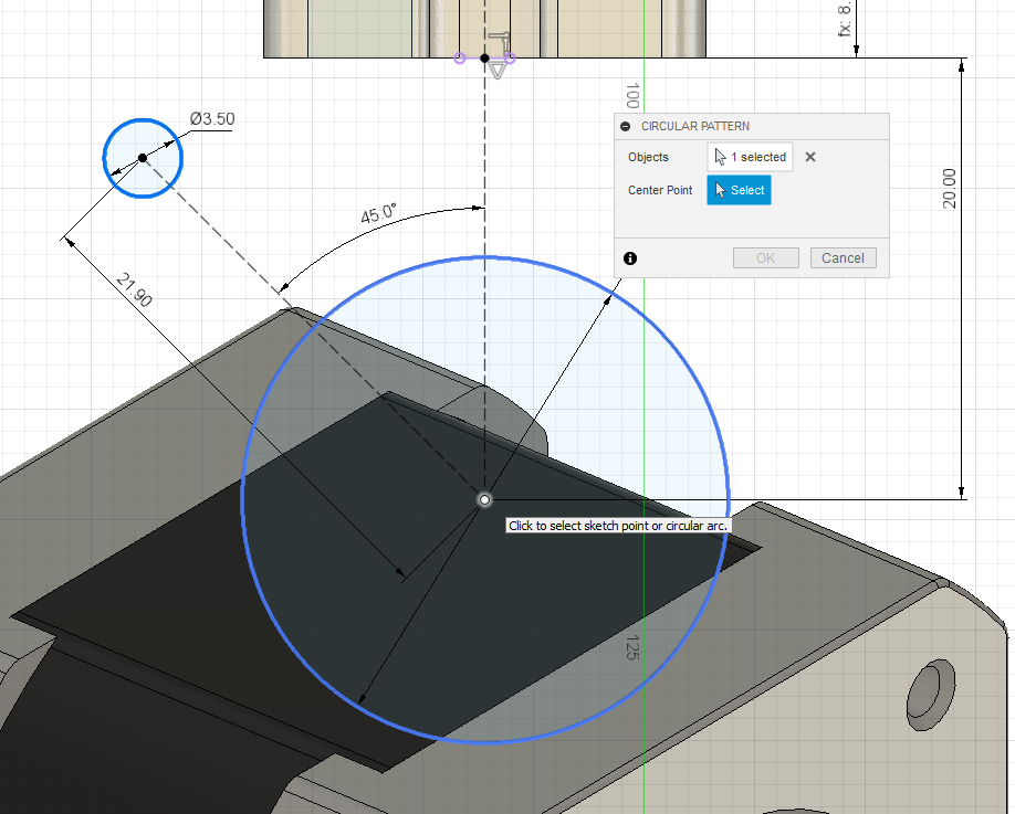
You just need to select the “center point” in the menu and then click the center of the big circle we made. This is the axis of rotation for the circle.
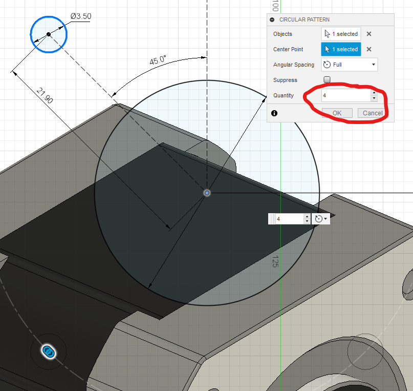
Remember to set the right number of total holes (4).
Now just make some lines to contain everything we just made.

These are super bad and not straight. Let’s fix them with sketch constraints. We can start with the coincident constraint to lock the corners at the top to the line formed by the outside edge of the extrusion.
Next we can use another construction line to keep these points in line. Hit “x” to switch to construction, “l” to make the line (ensure you are clicking on the points of the shape), and finally “x” again to disable construction geometry.
Next use the horizontal/vertical constraint to lock the line flat.
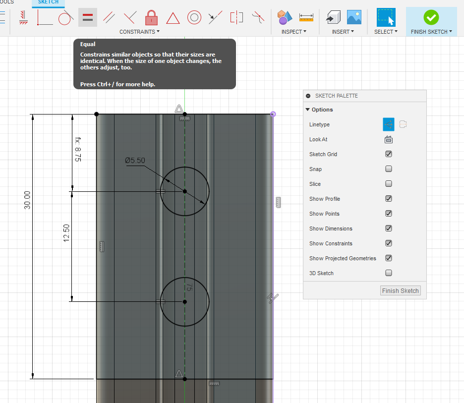
Next we can use the equal sketch constraint to make these two angular pieces equal.

Next we can use the coincident constraint to lock the construction line to the end of the extrusion.
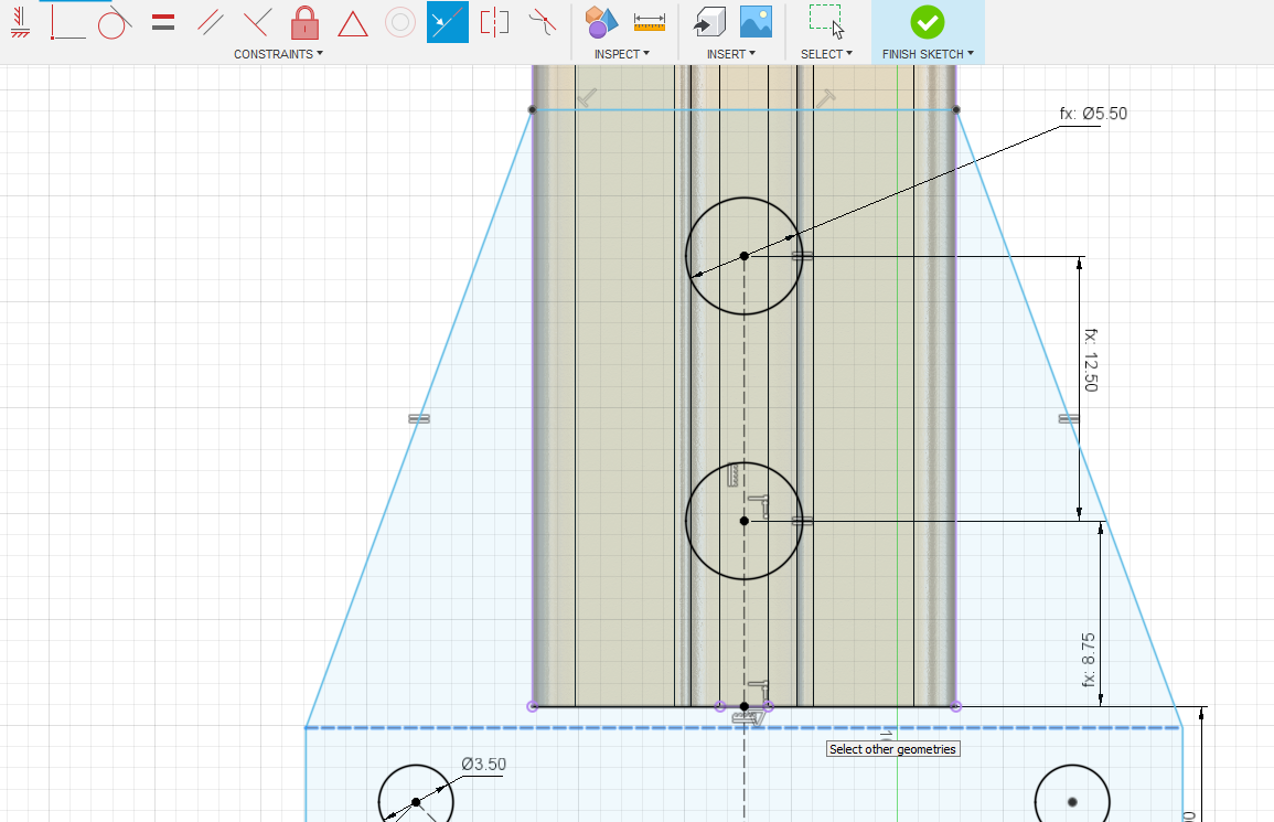
Mmmmm… Beautiful sketch. Let’s make it real. Hit finish sketch and then the extrude button. This time no tricks just grab all the profiles and extrude to 5mm.
Now joint the motor to the motor mount plate. You can use any of the outer rim holes or the center hole.
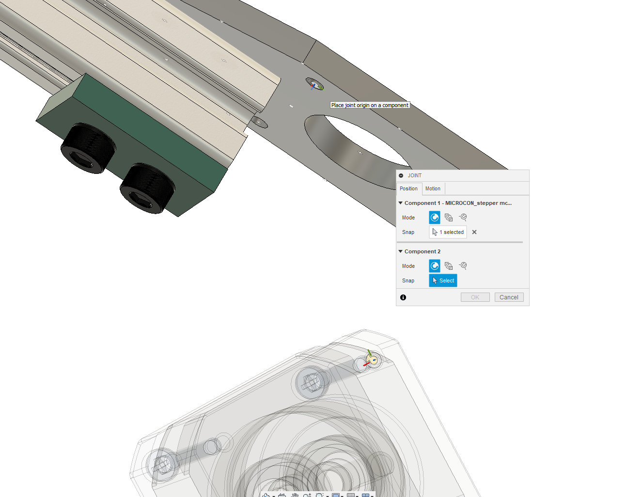
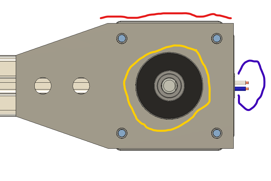
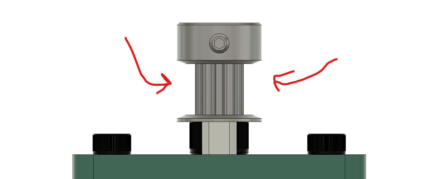
Now that it’s joined, let’s look at it. I noticed a few issues immediately. In red, the motor extends beyond the edge of the mounting bracket. This looks a little shoddy. In orange, this is waaaay too tight a fit. But in blue, it’s nice that there is room for the motor leads to leave the motor. I have definitely forgotten that before.
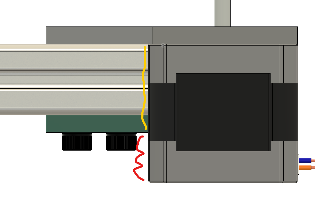
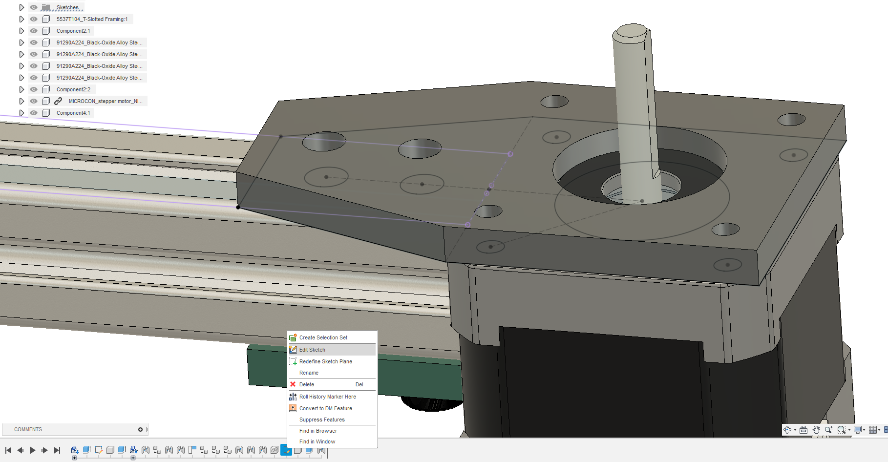
The side view again shows issues. The motor is too tight against the wall and our foot design is far too short. First things first. Let’s go in and edit the sketch again. It’s important to expect mistakes, look for them, and tackle them quickly.
Hit edit sketch on the timeline here. This can be more convenient than using the browser if you just sketched it.
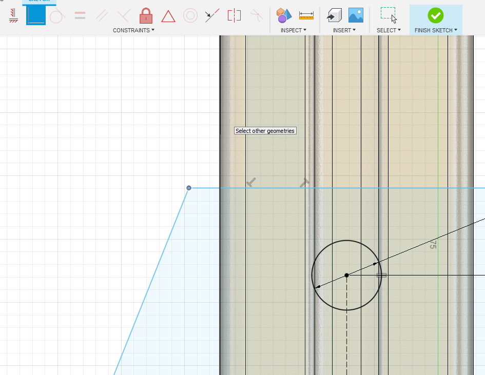
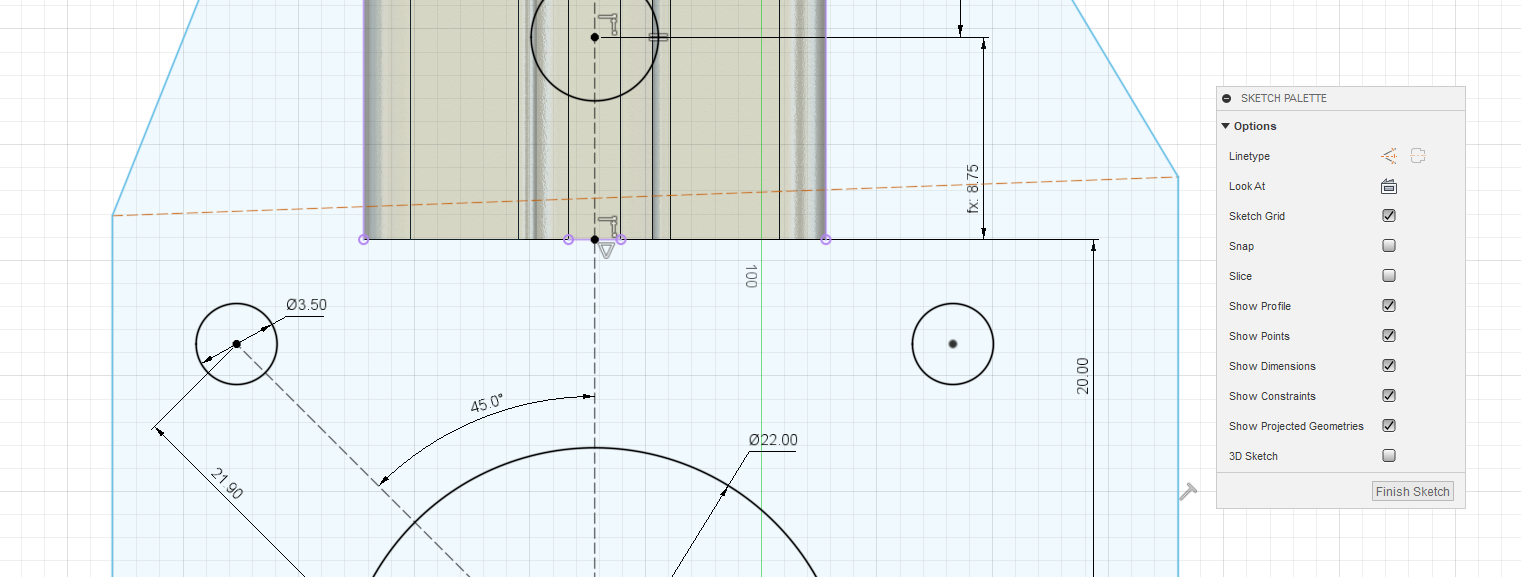
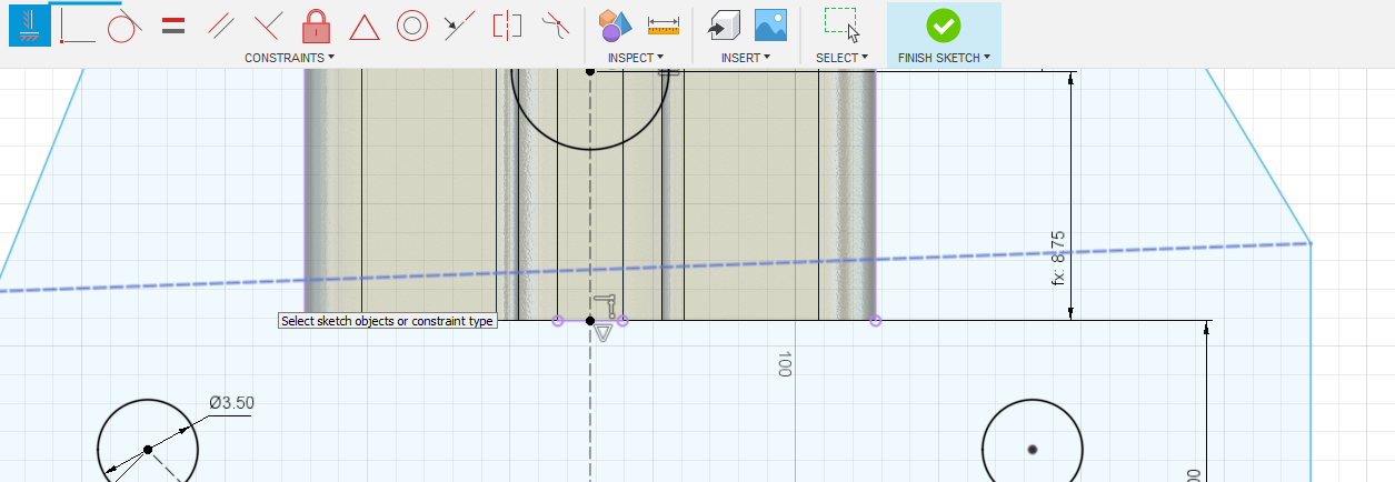
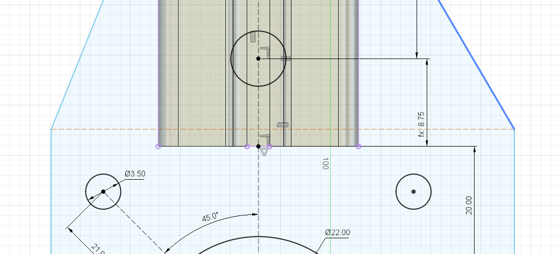
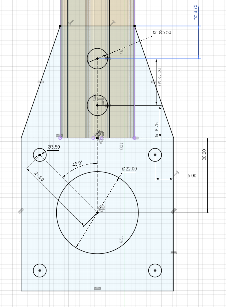
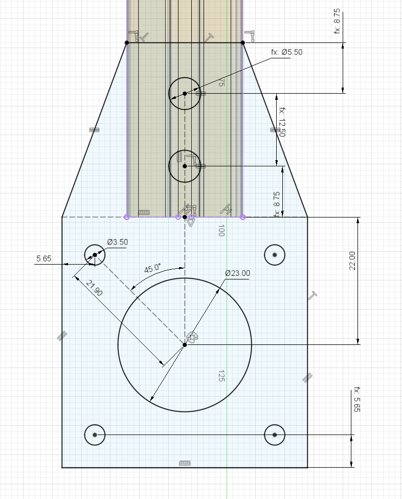
I changed the diameter of the big circle to make it bigger, changed the main offset to 22mm and removed the equal lengths of the square members in favor of a second bottom dimension. The specifics of how it works are less important than the final product.
Click finish sketch and look at the software automatically fix everything. What a nice looking motor mount.

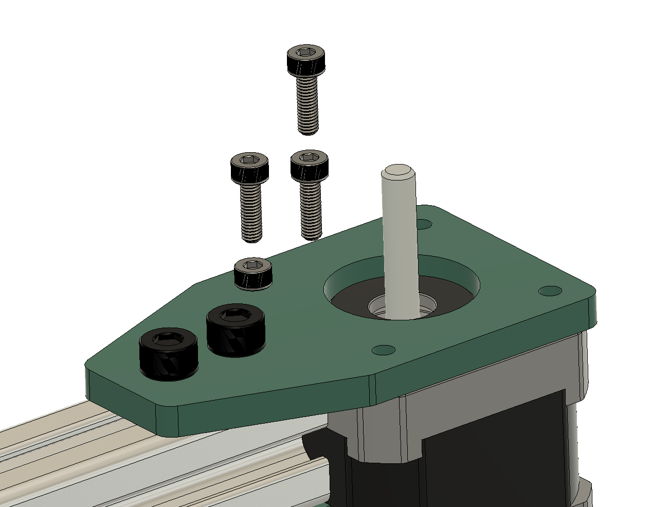
It now looks really nice and doesn’t raise any red flags for me. This motor will fit nicely in this mount. To celebrate before we deal with the foot, let’s add some flourish to the part. I used the filet menu and the appearance menu from before to make it look more polished. The motor mounts with M3 screws. Pick ‘em up from McMaster (10mm long)
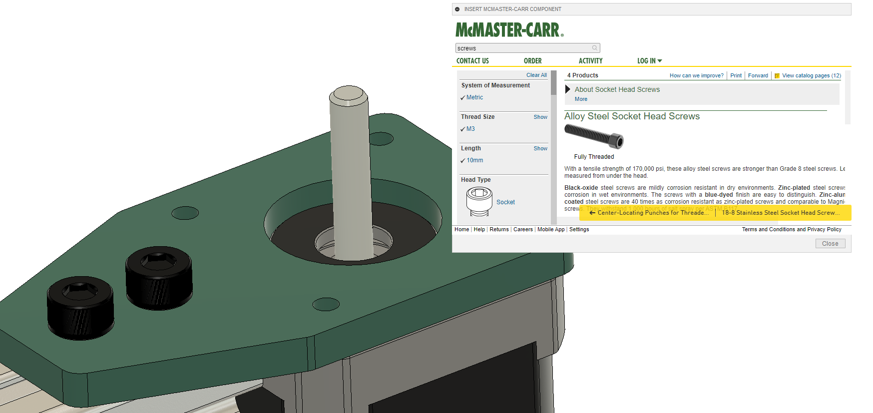
Copied and pasted the screws three times, colored them black, and used joints to position them in the holes.
Really looking great.
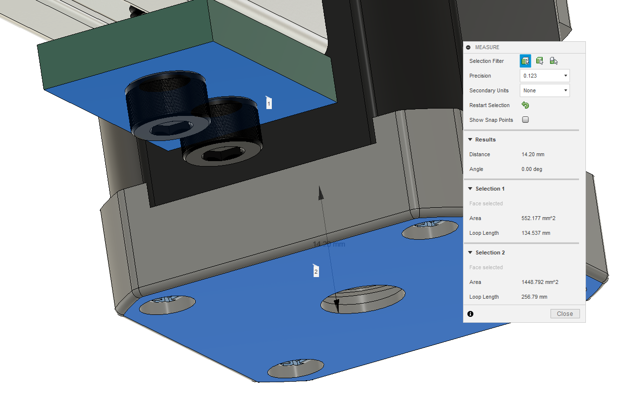
Let’s make the foot longer now. First we measure the difference to get a minimum foot value. 14.20mm. So the foot has to be longer than that.
I’m going to roll back the history to right after we first made the part in the timeline.
I made a sketch right on the plane the screw heads are resting on and made a circle bigger than the screw head around each of them.
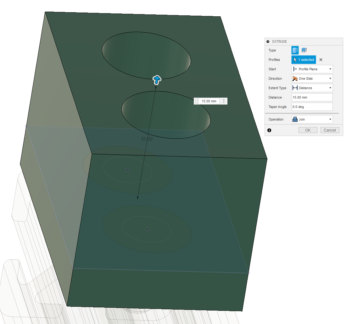
I then extruded the part around the screws out to 15mm.
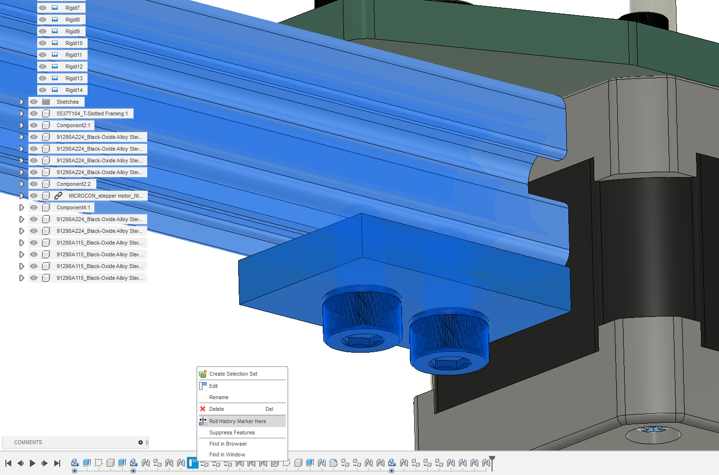
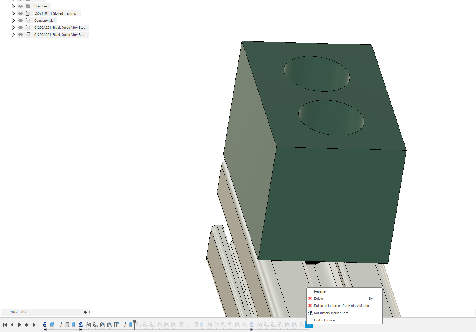
Now cut back to the current time in the timeline. “Roll history marker here”
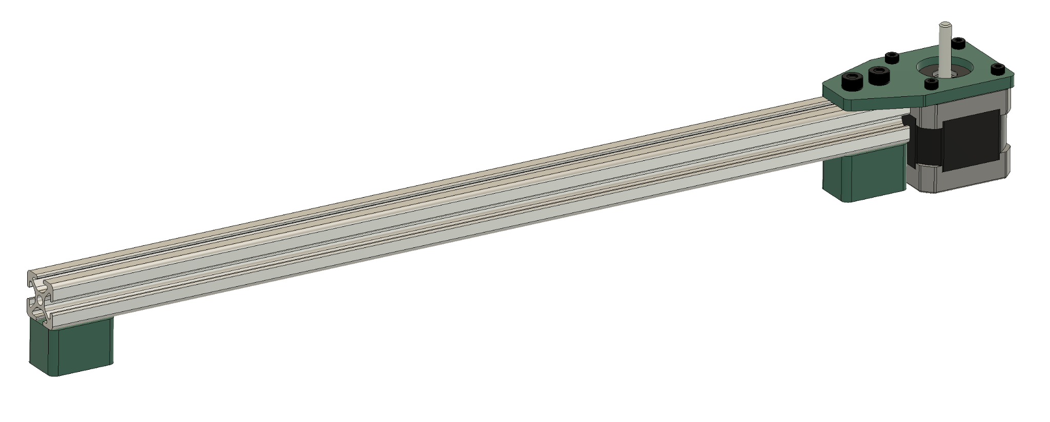
It is really starting to look great. I mean that. You’re doing a great job.
Now we have a structure, a finished motor mount, and a motor to play with. Let’s get the last round of parts before we’re finished. We’ll need a cable pulley for the stepper motor, the same pulley but a version with bearings instead of one designed to lock into position around the motor shaft, and we’ll need some bearings that can slide in the aluminum extrusion. This kind of 20mm profile is often called 2020 for short. As usual, you can rely on McMaster for it but if you actually want to build this in real life, one can often find cheaper versions of these parts on other sites with slightly different configurations. Note that this configuration has a belt idler with a larger diameter or number of teeth than the pulley. This will cause a slight discrepancy in distance traveled by the end effector. This can be tuned out with step calibration but if you want to build the real thing, find an idler with the same number of teeth. Sets of these are ubiquitous on platforms like Amazon from companies with lesser reputations. For our purposes those will work fine.
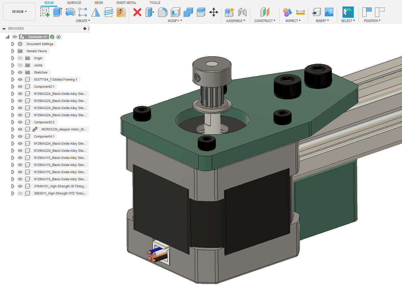
I joined the cable pulley to the motor head here. It is high on the motor shaft to avoid hitting the bolts securing the motor in place. Check to see that it actually clears them.
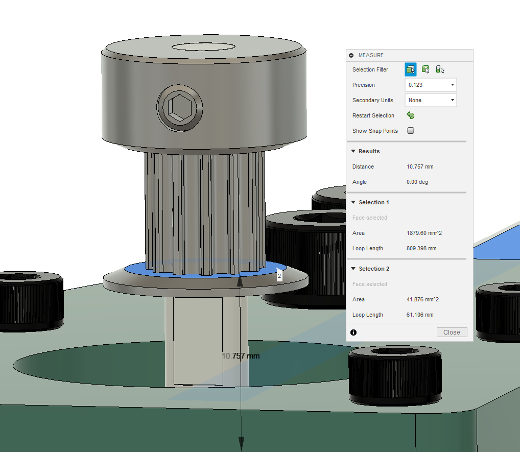
Now measure the offset from the flat top of the extrusion to see how far to mount the idler on the other side of the extrusion.
We’re going to start moving faster now again as you start to understand the process. The next part needs to hold the tensioner / idler for the pulley. Included is the usual highlighted part from the drawing.
I made this sketch for the bottom.
I then extruded it out to 5mm and made a second sketch plane on the top plane of the newly extruded part.
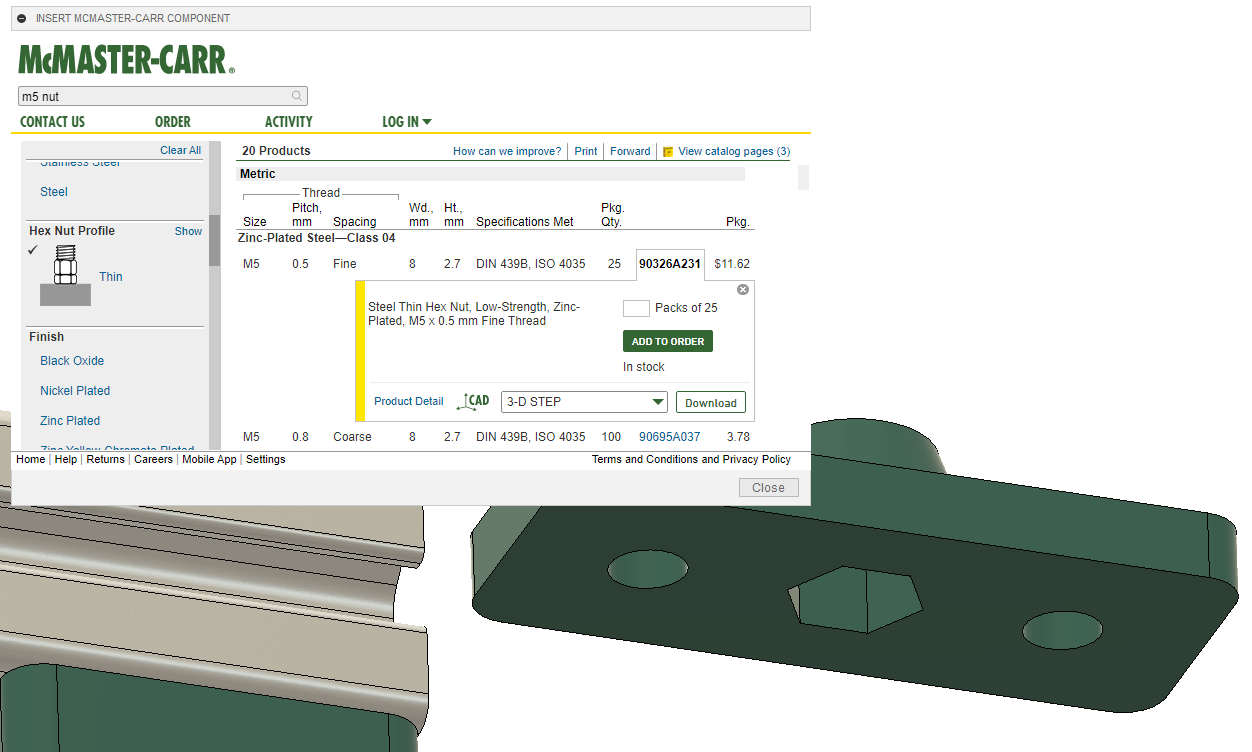
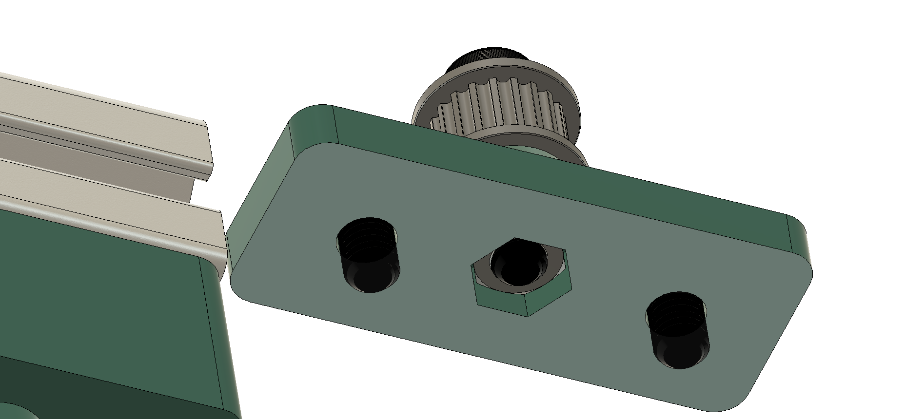
Now make a simple sketch to adapt the M5 nut securing part to a hole for the idler securing screw. Read further if this doesn’t make sense so you can see it come together in picture form.
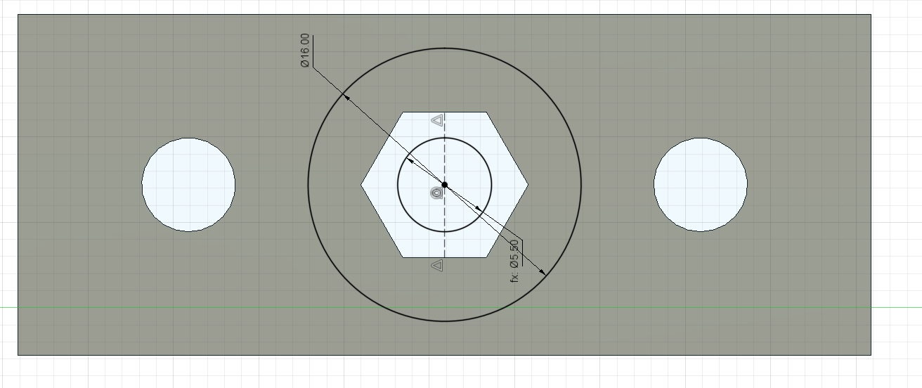
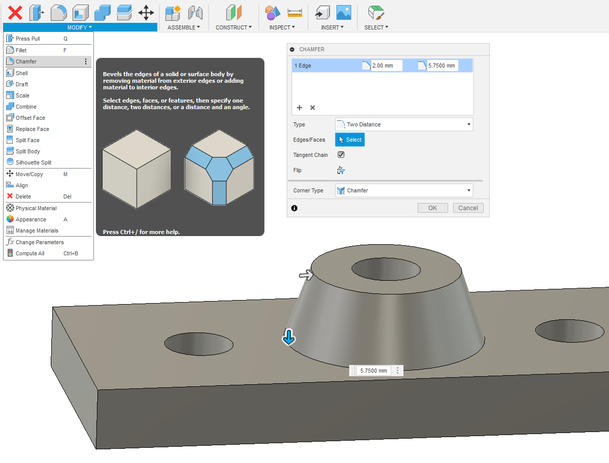
Extrude the outer circle through to the inner circle the distance we measured - the 5mm of thickness already in the bottom and the 1.2mm thickness of the bottom of the idler. This comes out to 4.55mm despite what the image says. I made a mistake forgetting to account for the pulley thickness.
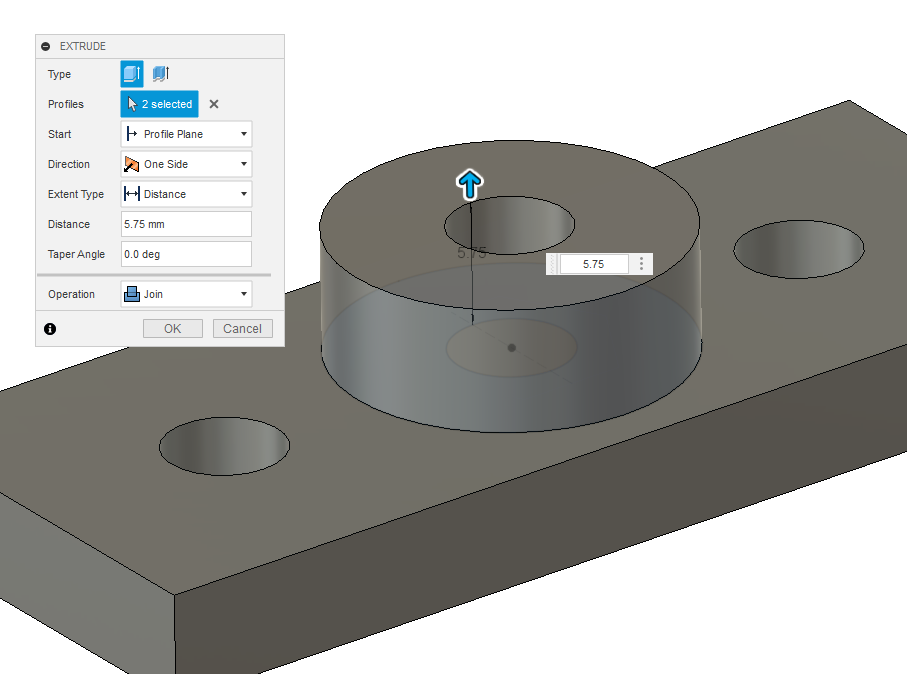
Correction: this height should be 4.55 (5.75 in the image was a mistake I fixed later in mine) to account for the rim of the pulley. I added a chamfer here (like a straight fillet) to make it look better and use less material.
This bottom height should also be 4.55. I textured it and added a nut from McMaster for the bottom
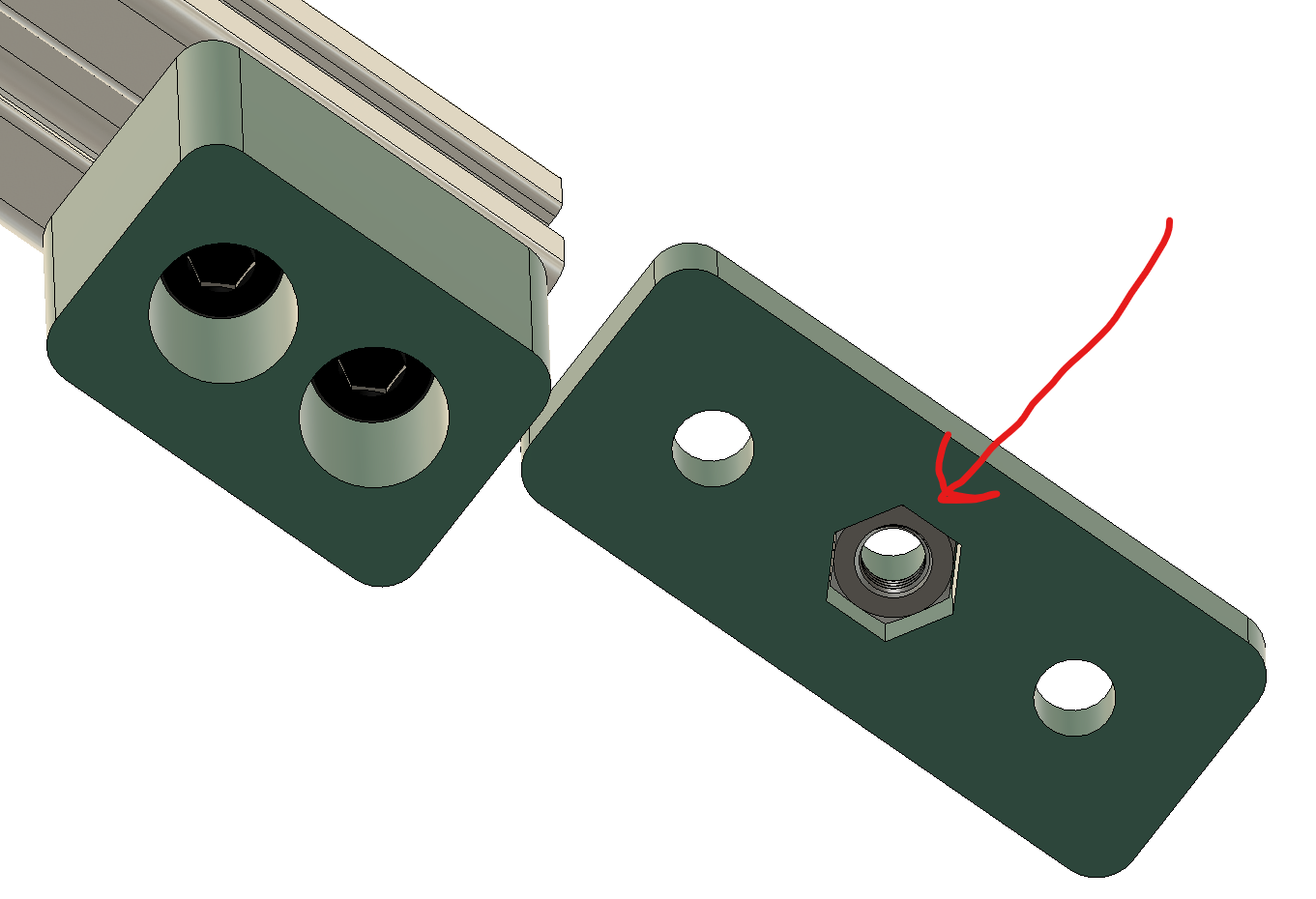
Made sure the nut was properly joined to the part.
I then took the idler and joined it to the top. But it still needs a screw to mount to. I measured the distance between the top of the pulley and the bottom of the part for a maximum screw length and went to McMaster for it.
It is really starting to come together.
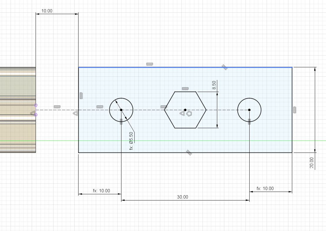
The final part is a slider block for the extrusion. The drawing below shows the initial size.
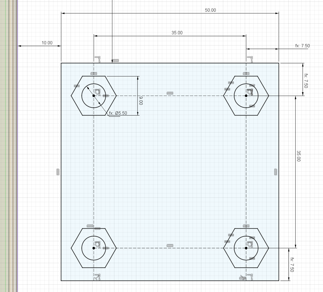
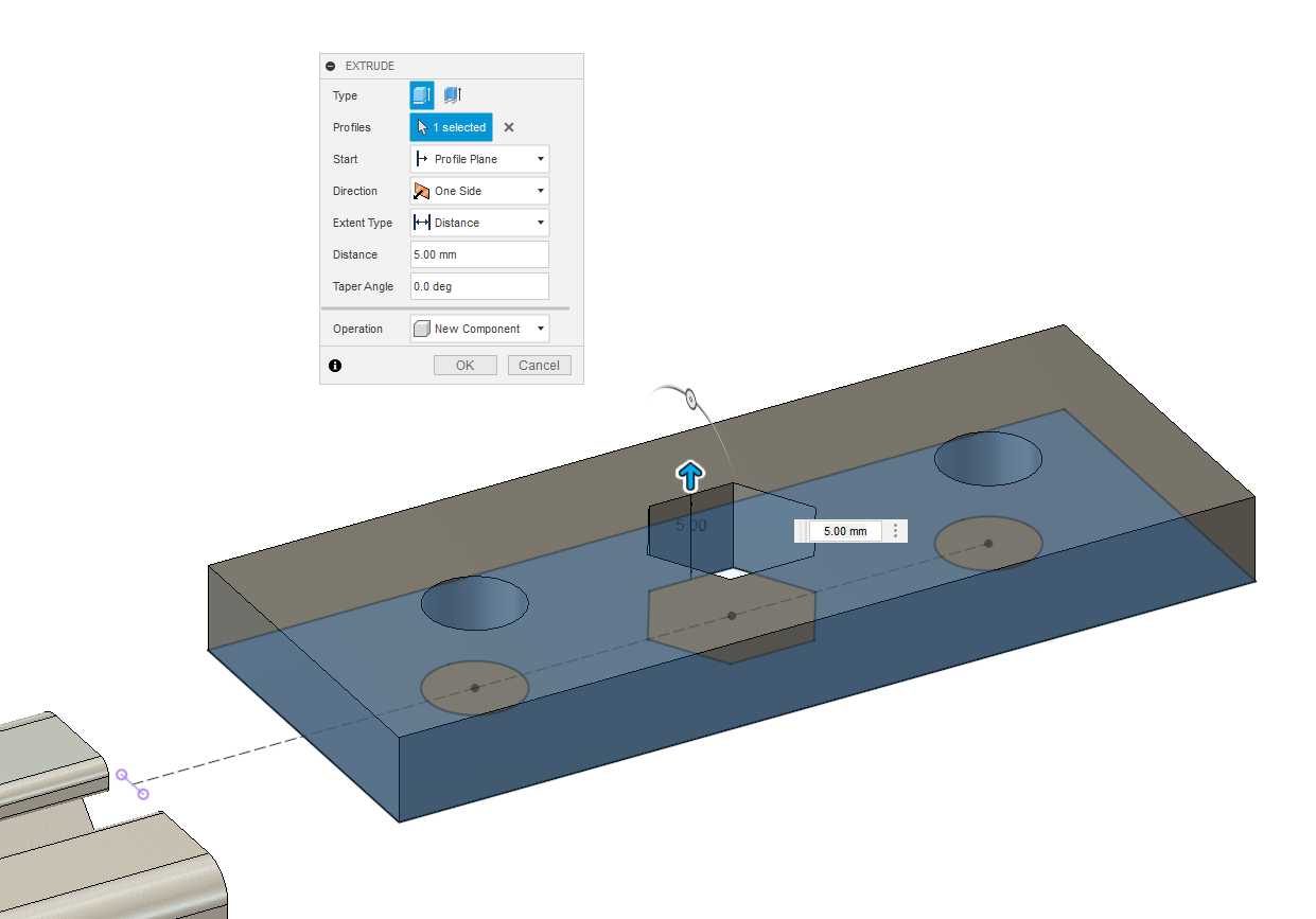
I also added lines centered at 21mm apart to my drawing for a slot so the part wouldn’t interfere with the extrusion. I extruded one side up with the hex holes cleared out. I also forgot to make this a new component, not just a new body. We’ll deal with that in a minute.
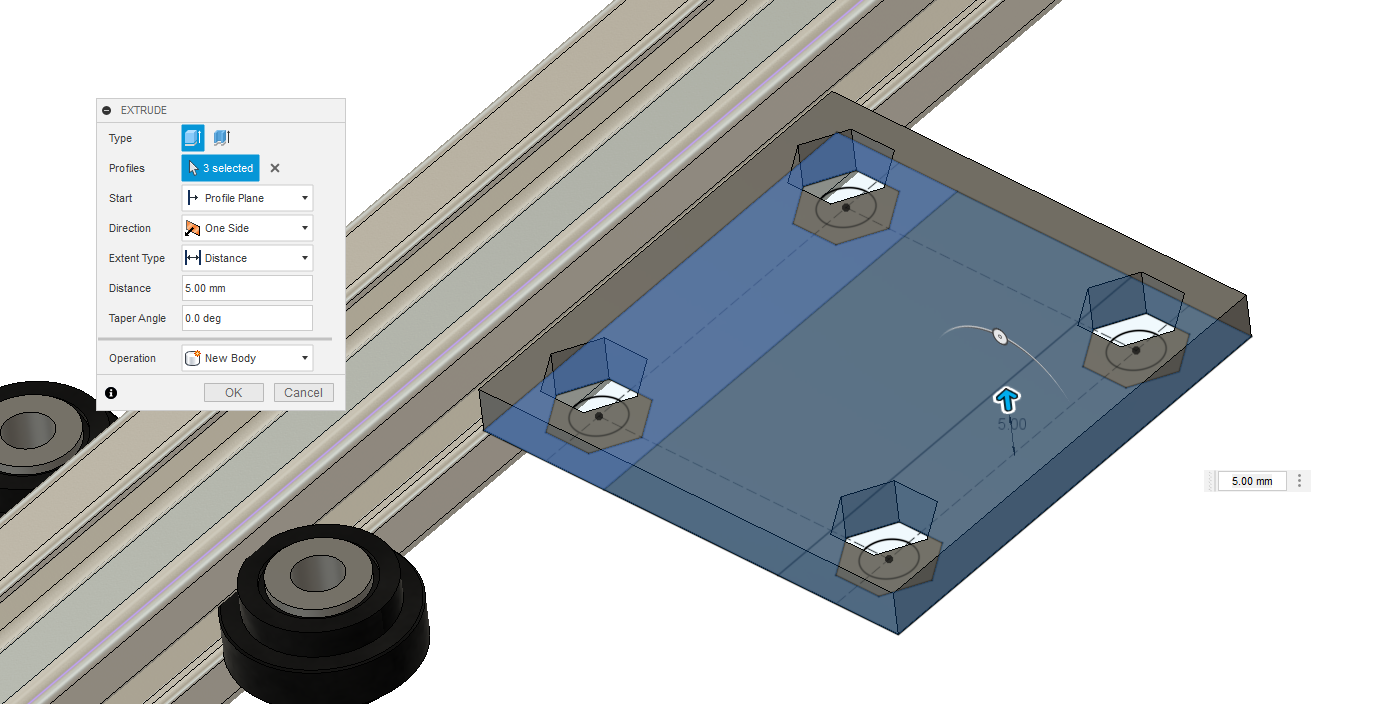
Then, since the first extrusion made the sketch automatically disappear, I made it visible again so I could extrude different geometry on the other side of the part from the same sketch.
I then made a second sketch for the last part because I was slightly lazy. It is possible and fairly easy to make this part in one sketch though.
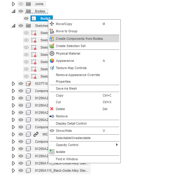
We can fix that body/component mistake by expanding “bodies” in the browser and clicking on create components from bodies.
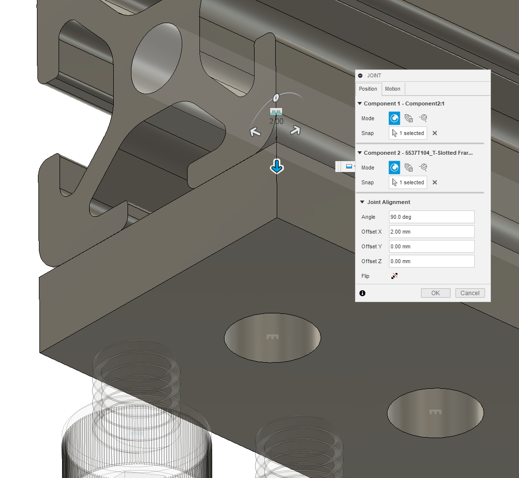
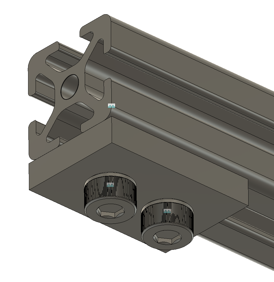
I colored it, added chamfers & fillets, brought in the correct parts & joined them, and prepared for a new type of joint. Click one of the ends of the new cart part as the first part of the joint.
Next grab the top front point of the motor controller.
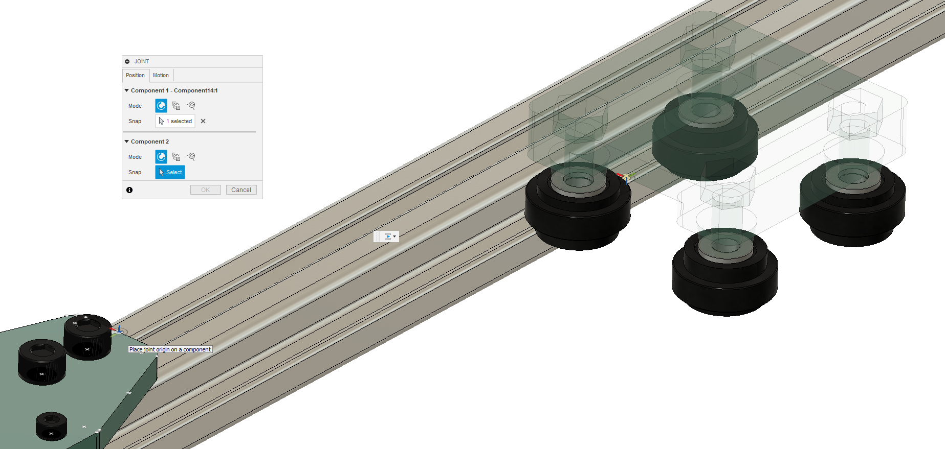
If you’ve done this successfully, your joint will make the two pieces join at the front as shown below. But not all is finished yet. If you go into the motion tab of the joint menu and select “slider” you can set the motion platform to move back and forth in the Y. The motions will have a short animation to demonstrate what axis is moving. This can be useful as our axes may not be consistent.

Now you can click and drag the table around to move it.
Finally, we can jump over to the render workspace.
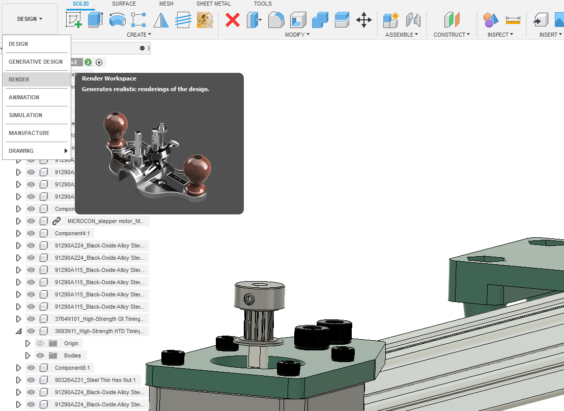
Select scene settings and move around the position of the environmental light to make some nice glossy reflective surfaces shine.
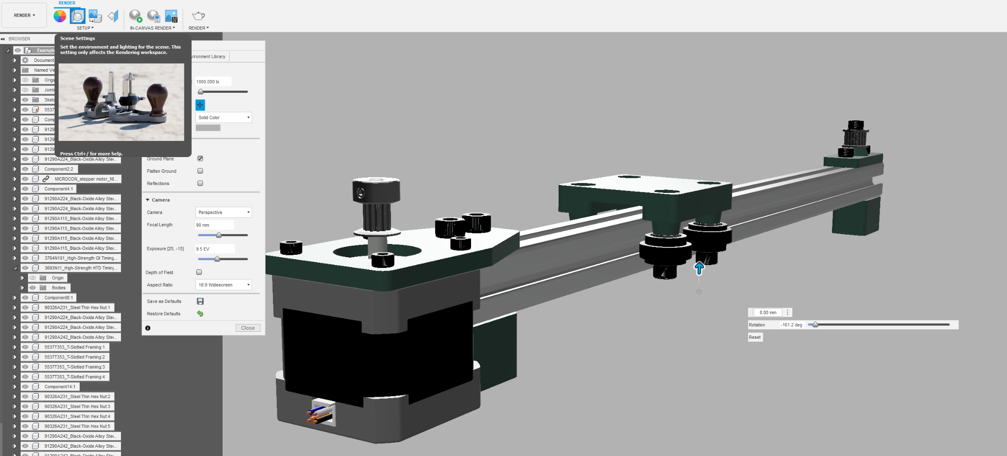
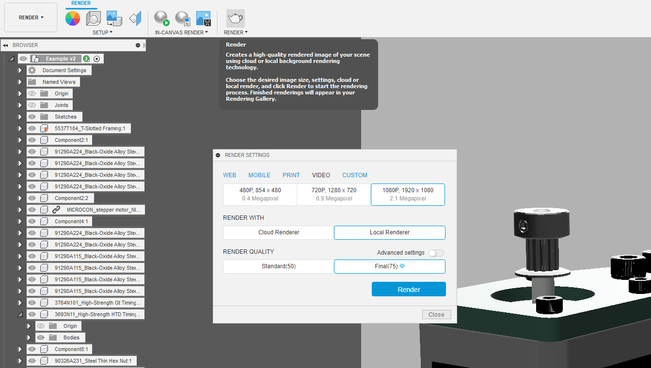
Hit the render button in whatever aspect ratio you like. If you have a student license, you can have autodesk do the actual rendering computation and it’ll probably look better. Just remember to set the resolution how you want it. Hit the big blue render button in the bottom right corner and wait a few minutes.
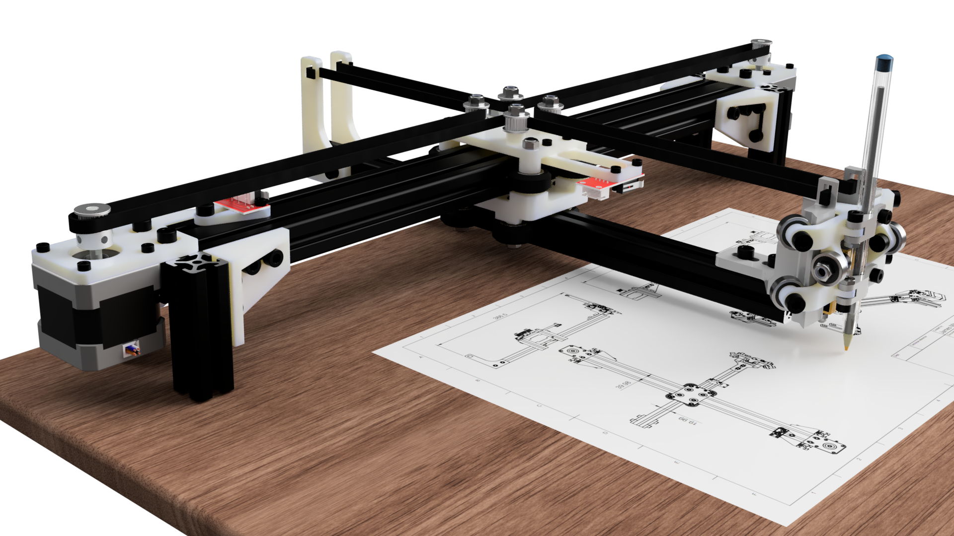
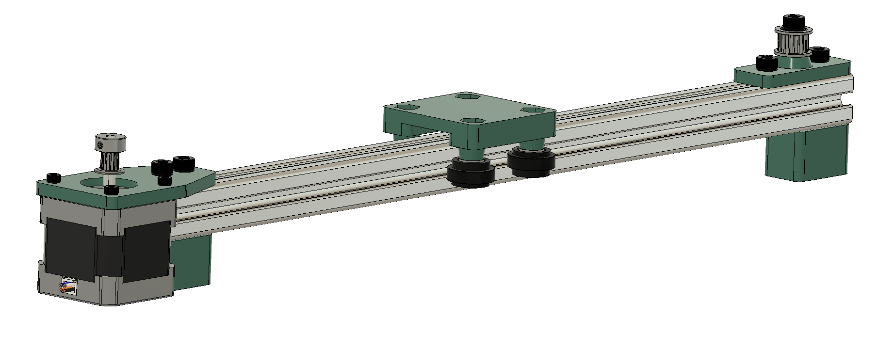
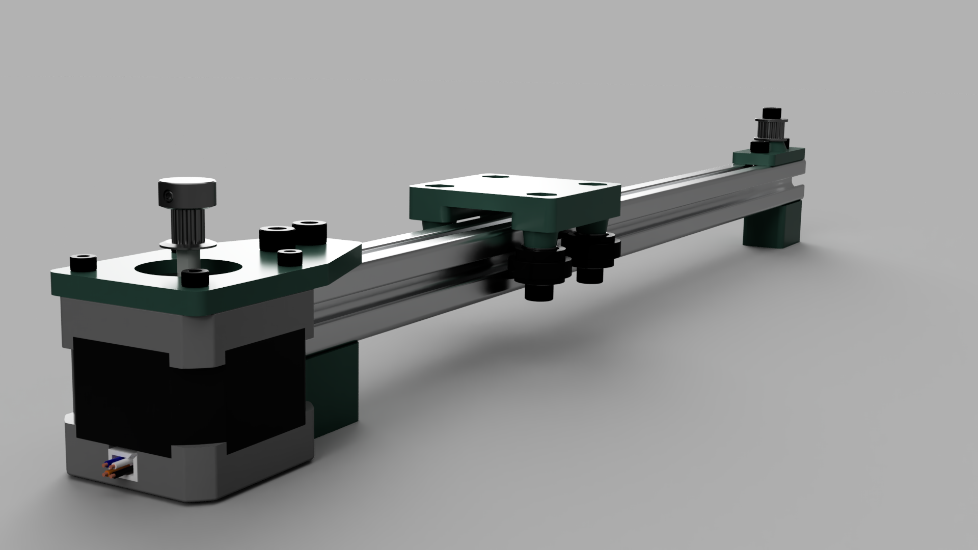
And violà! We have a finished product. Looks a lot nicer than that first drawing, but which took more time?
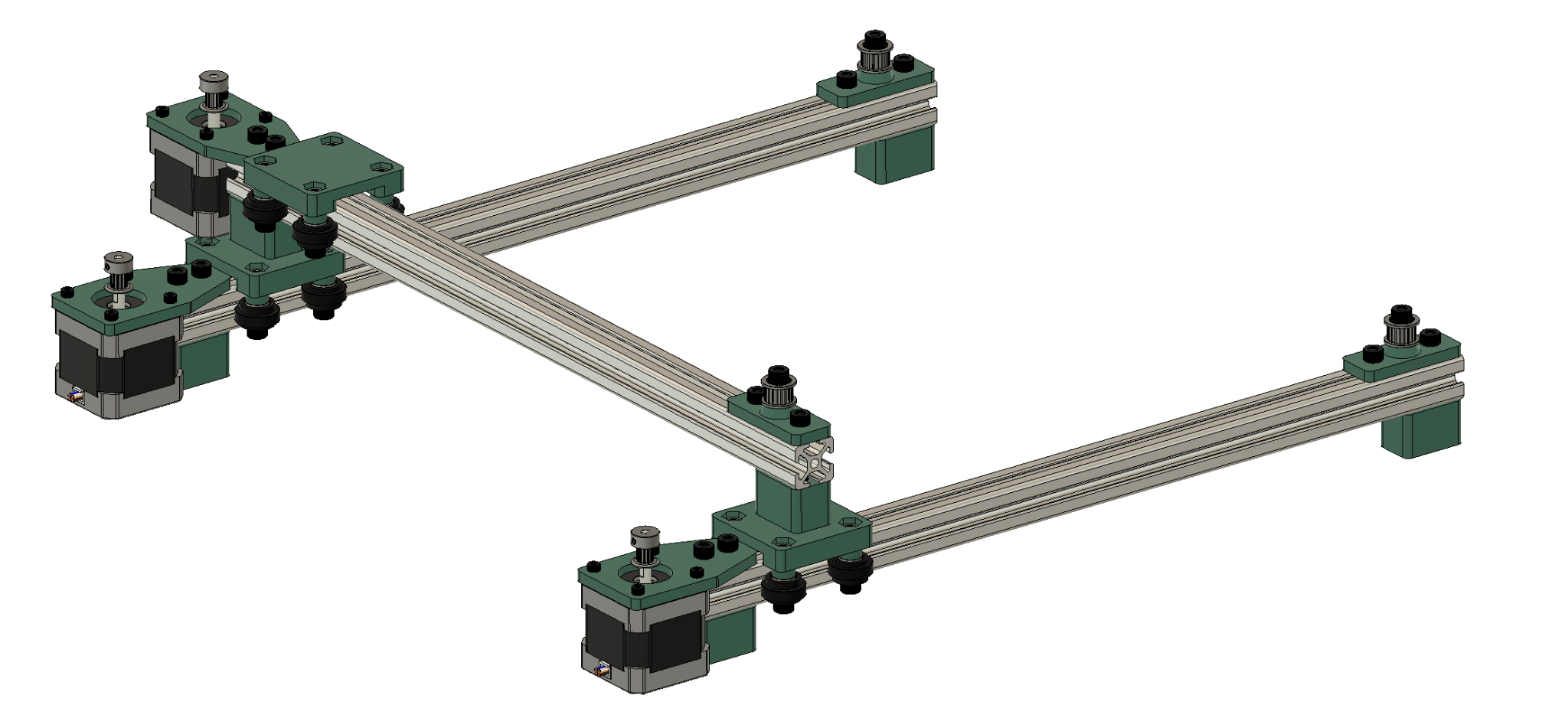
A ton of re-configurations are possible just watch out for the belt routing.
It is through this method that I arrived at a slightly modified final design for my project. Okay so you have the basics of CAD design in the book. What resources are there to go further and how do I know my parts will work after they’ve been manufactured? The answer to the first question is just put time into it. Find project ideas that interest you and figure out what buttons do. As for the second question, let’s talk about design for manufacturing.
4. Design for Manufacturing
1. Introduction
This section is designed to help fill the gap between experienced 3D printer users and those who are just starting out. Ideally, making up for the experience of making lots of parts that don’t work without wasting as much plastic in the process.
Structure:
-
3D Printing
-
How does it work and where doesn’t it
-
Tolerances and making reusable parts
-
What is slicing and how to do it
-
Plastics that are generally available and why to choose one over another
-
-
CNC Milling
- Really brief overview with other resources
2. 3D Printing
The Basics
3D printers lay down plastic in thin lines that bead together as they dry, forming a strong bond. These bodies can be very complex and customizable as long as they are smaller than the build area of whatever printer you are using (typically a 20cm edged cube). But keep in mind that FDM printing is really slow and can be less accurate than other forms of manufacturing. 3D printers are most accurate in the X-Y plane. With distortion and layer thickness reducing the resolution. So you may be tempted to design parts in thin assembly ready plates that utilize the accuracy constraints on the Z. That is the smart way to work. But instead of 3D printing those parts it is better to cut them out on the laser cutter because thin wood is often stronger than thin plastic and importantly the part will come off the bed in far less time. But if you are set on 3D printing, then understand the differences between the plastics and the significance of print slice settings.
Designing Parts to be 3D Printed
Geometry
Bridging
Is when the printer has to lay out plastic between two supported points. This causes the plastic to sag in these places during the printing process. This process happens the most on vertical axis holes found in the walls of items printed going up on the Z-axis.
Solutions:
-
Make the distances involved really small.
-
Use support material, which will be generated by the slicer.
- Support material is additional plastic extruded to ensure that the part doesn’t sag, it is then removed after the printing process. Removing it can be hard without damaging the part and it will always leave a mark on the surfaces it has been removed from.
-
At the end of the day, some sag or marks will always be noticeable on parts unless the bridges are reduced to 0.25”/5mm or less.
-
3D hubs suggests that an advanced solution is to separate a part into several pieces to be assembled after printing.
Vertical Axis Holes
When you put a hole in the side of a 3D printed part, be ready for the hole to be under size by a decent margin.
The reasons for this are fairly simple (3Dhubs). As the nozzle prints the perimeter of a vertical axis hole, it compresses the newly printed layer down onto the existing build layers to help improve adhesion. The compressing force from the nozzle deforms the extruded round layer shape from a circle into a wider and flatter shape (see image below). This increases the area of contact with the previously printed layer (improving adhesion), but also increases the width of the extruded segment. The result of this is a decrease in the diameter of the hole that is being printed. This issue is particularly bad, when the holes are smaller relative to the nozzle. Think 3mm holes.
This effect can be accounted for in slicers and even on printer firmware, but since you are likely working on educational equipment. Expect the worse end of that spectrum.
Solutions:
-
If the diameter is not critical, aka the bolt/screw needs to be a slip fit, then just make the hole oversized in the slicer.
-
If the diameter needs to be exact, CAD the hole actual size and then drill it out when the print comes off the bed.
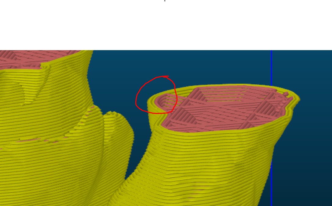
Overhangs
This is an annoying one. Overhang causes a lot of problems in FDM printing. It occurs when a material is printed only partially supported by the layer below. It is a lot like bridging but more troublesome. It is normally fine to print up to 45 degrees. As you can tell at 45 degrees a new layer is half supported by the previous layer. Note that a side effect of this is uneven cooling causing the tip to trend towards drifting up.
Solutions:
-
Similar to bridging, use supports or prepare for the worst.
-
You can also avoid this by designing parts without overhang.
Corners
Keep in mind that no 3d printed outside edge is ever going to be
perfectly square because the nozzle extruders cylindrical plastic. (Most
machines have a 0.4mm nozzle, though it is replaceable and smaller ones
can be purchased making this issue smaller and less noticeable.) This is
important if you are trying to design parts to slide together. Another
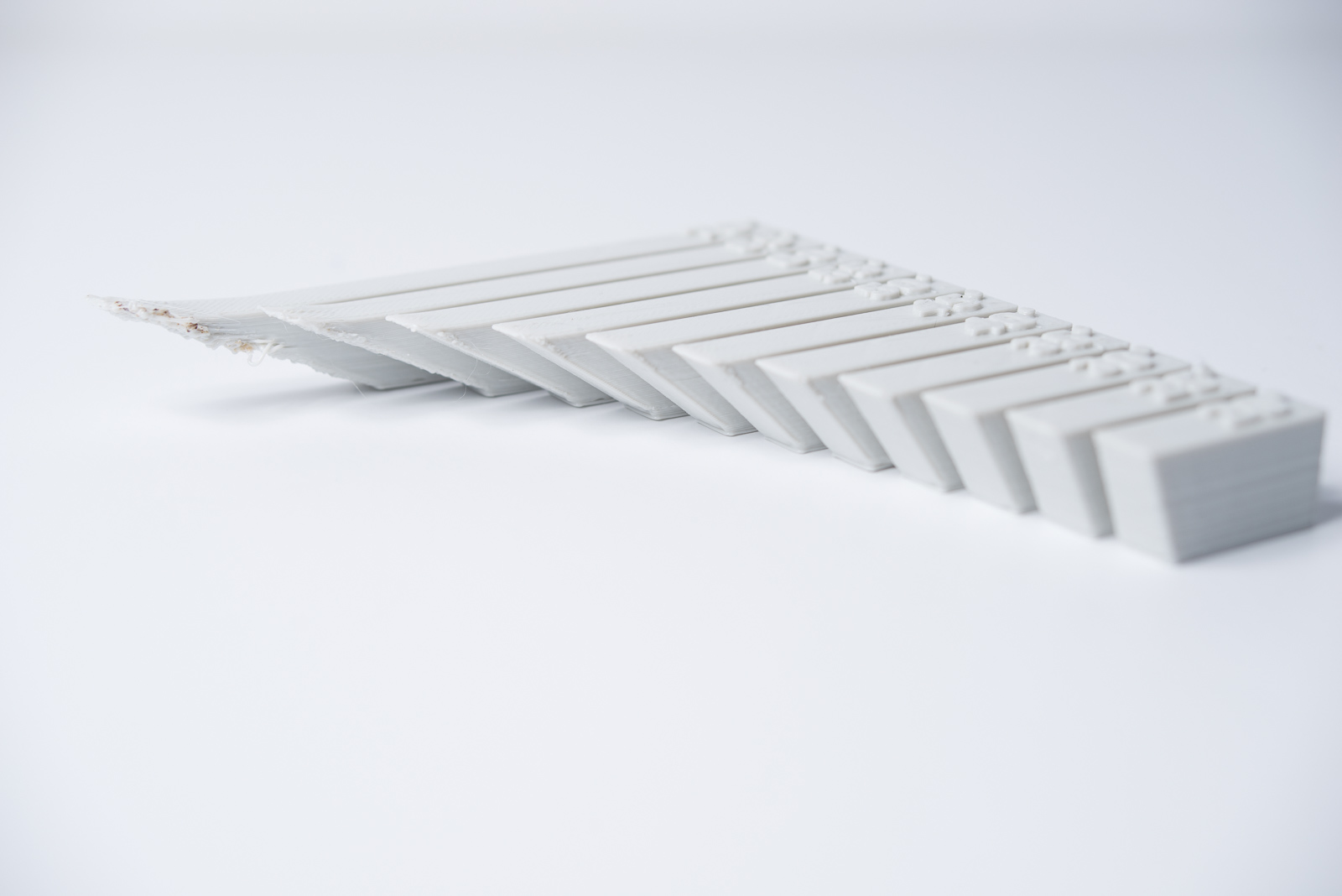
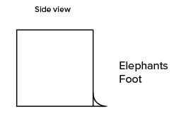
important factor is this weird effect called elephant’s foot. Wherein
the first layer of the print is pushed into the bed by the nozzle
causing it to spread out a little over the rest of the wall.
Solutions:
- 3D Hubs: If assembly or overall dimensions are critical to the function of an FDM part, include a 45o degree chamfer or radius on all edges touching the build plate. For high precision form & fit testing, use a different machine or be ready for some trial and error.
Fitted Pins
Think the top of a LEGO stud fitting into another. These features are often used to ensure that parts designed to press fit are lined up properly. To shorten a lot of information. Always make them >5mm in diameter, otherwise they will be extremely brittle. This really goes for all small features. Make them big enough to be useful.
Solution:
- If you need a really small pin, add a fillet at the base to shift the stress point up the length of the rod.
More Advanced Stuff
Rules of Thumb
3D Hubs gives this convenient list of rules of thumb:
-
If a bridge exceeds 5mm, sagging or marks from support material can occur. Splitting the design or post-processing can eliminate this issue.
-
For critical vertical hole diameters, drilling after printing is recommended if high accuracy is desirable.
-
The addition of support will allow FDM printers to print wall angles greater than 45 degrees.
-
Include a 45 degree chamfer or radius on all edges of an FDM part touching the build plate.
-
For applications with small vertical pins, add a small fillet at the base or consider inserting an off the shelf pin into a printed hole instead.
-
Splitting a model, re-orientating holes, and specifying build direction are all factors that can lower cost, speed up the printing process, and improve the strength and print quality of a design.
Hole Tolerances and Integrating reusable fasteners
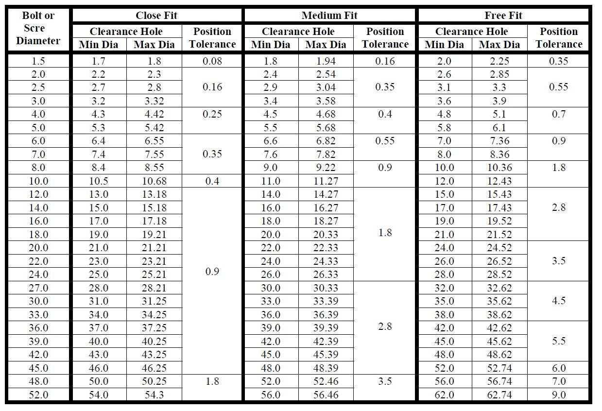
Fig 14, table of tolerances for different diameter holes (mm). Note this might be a little different depending on the 3D printer you are using. Always a good idea to oversize things a bit.
Charts like this provide really nice numbers for manufacturing and CAD based on what you want to use the screws for. Keep in mind the top, where it says close fit, medium fit, and free fit. If you want a chart like this for non-metric screw sizes… Don’t use non-metric screw sizes (or google it and be judged by future generations for millenia to come).
Attaching several 3D printed parts
-
Bolts and Nuts
- Reliable, cheap, simple, somewhat inconvenient
-
Bolt and heat-set inserts for plastics.
-
Reliable, expensive, simple convenient
-
They are typically bronze and are very simple to use. Just over size your hole to the spec of the manufacturer and then set the thread insert onto the hole and place a hot soldering iron onto the top. It will soften the plastic and the thread insert will slide in. Once it is in place, remove the iron and gently blow on the plastic around the threaded insert.
-
-
Super glue/solvent
- Excellent solution though difficult to undue and can be messy.
-
Welding
- Plastic welding is really easy and a fun way to get a strong connection between two or more pieces. Pick up a plastic welder or just use a discarded soldering iron. Run the warm tip along the seam until you cannot see between the parts.
-
Friction
-
Be careful on this one, it is a little difficult to explain to an authority figure.
-
Place some discarded filament into a dremel tool and spin it up while applying light pressure to the joint. While it will require some practice and experimentation, it can provide a fast, wireless way to connect stuff.
-
Slicing 3D Prints
File Selection
All 3D prints start with a 3D model, that model is generally in the .STL format. In order to send the model to the printer it has to be sliced, or converted into motion coordinates for the machine to interpret. This process is called slicing and the programs that do it are called slicers. This is useful as frontend information because lots of settings between you exporting a 3D printed model and the model going to the printer can be edited or optimized for strength or weight. The main ones to consider are:
Infill percentage
Infill percentage is almost certainly the most important characteristic to manage while slicing a new 3D Print. It is the amount of plastic fill that is used inside of the part. 20% infill is strong enough for the majority of 3D prints which is why that is the default setting on almost every slicer. If you need to make a very light part you can drop the infill or if you are making a very small load bearing part, you may need to increase the infill. Note in the figure below the red lines inside the outer shell on the left figure and then their disappearance on the right. That is the infil level going from a geometric 20% to a barebones 0%. Basically the stronger you need the part to be, the higher the infill should be.
Coordination or relative position (and supports)
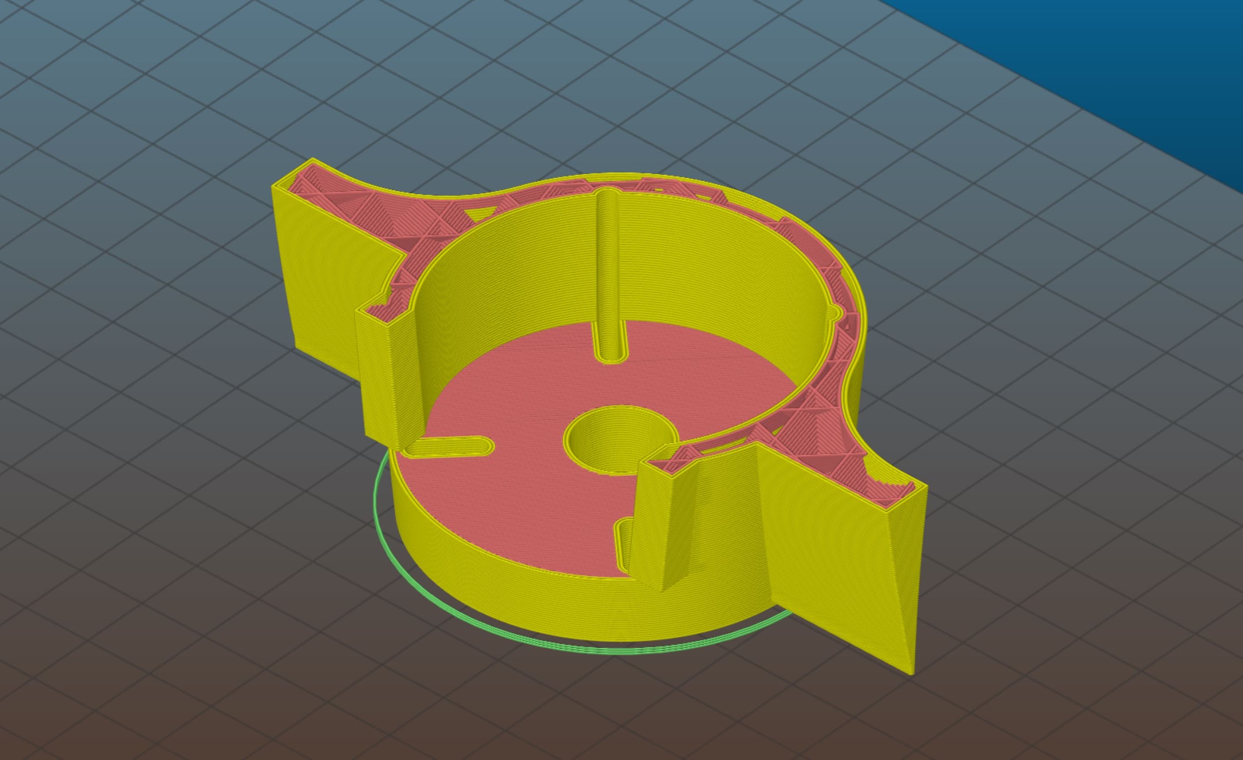
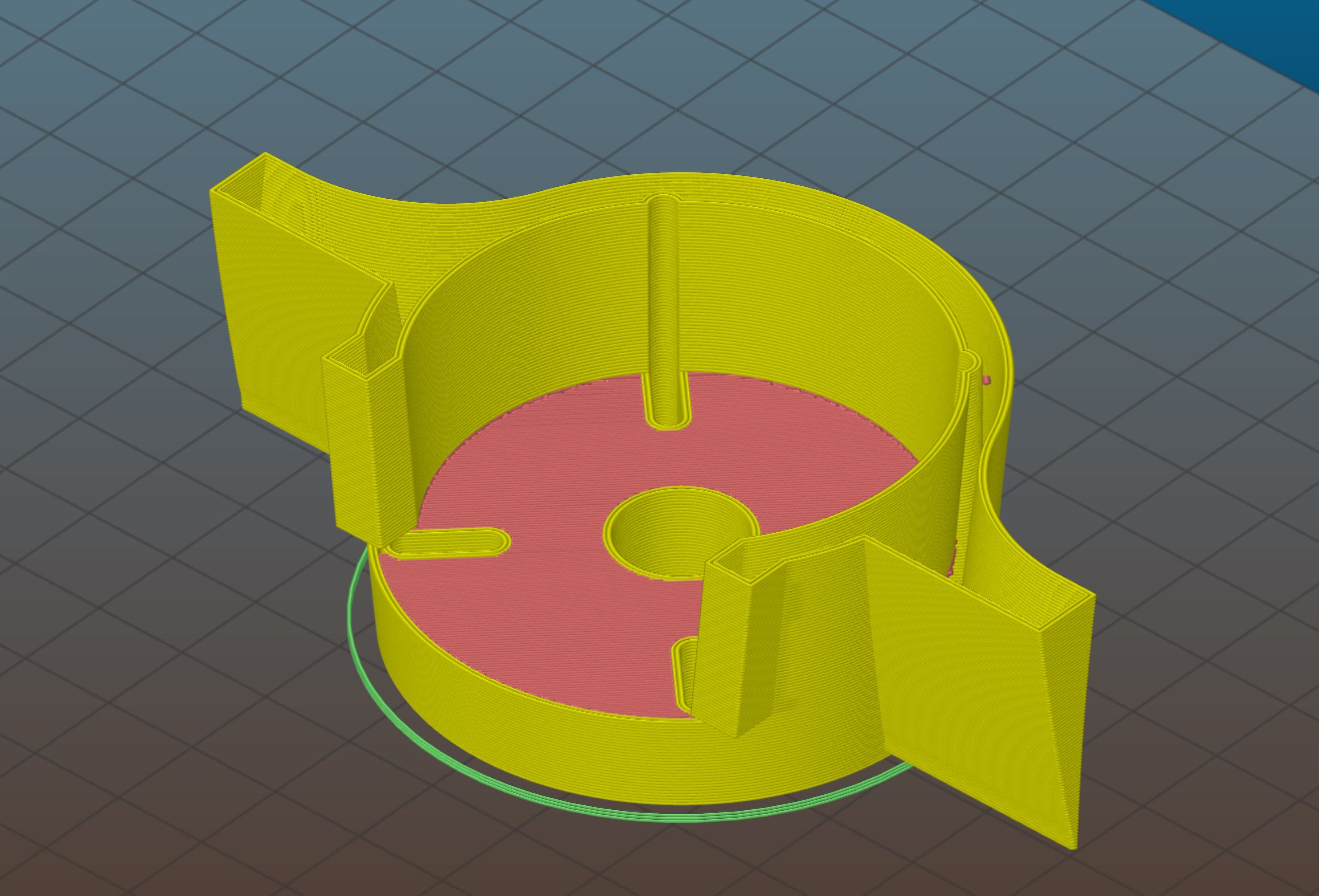
This one is simple but important. As mentioned earlier, the printer has the most resolution on the ground X-Y plane. So it is an important decision how the part is oriented. Ideally orientation of printing has been a consideration throughout the design process. The sooner you think about this the better. Note in the figure to the right how the layers going up are very low resolution. Causing the outside of the drum to be very rough. Features that require accuracy in the Z axis are going to be rougher than those that only require accuracy in the X-Y axes. To further illustrate this, notice how the circle in the next figure is much smoother.
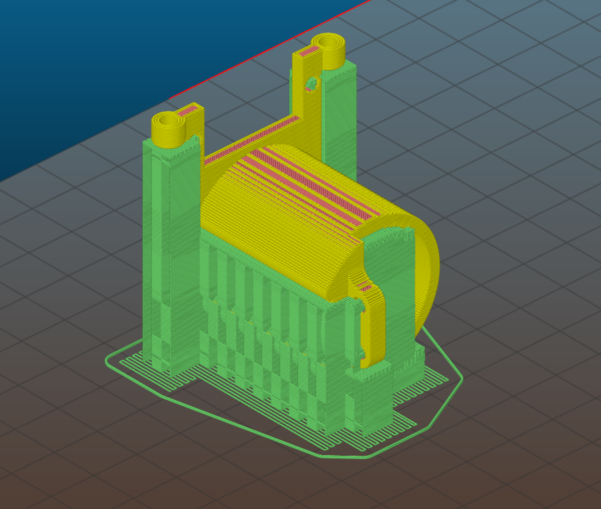
Shell Thickness
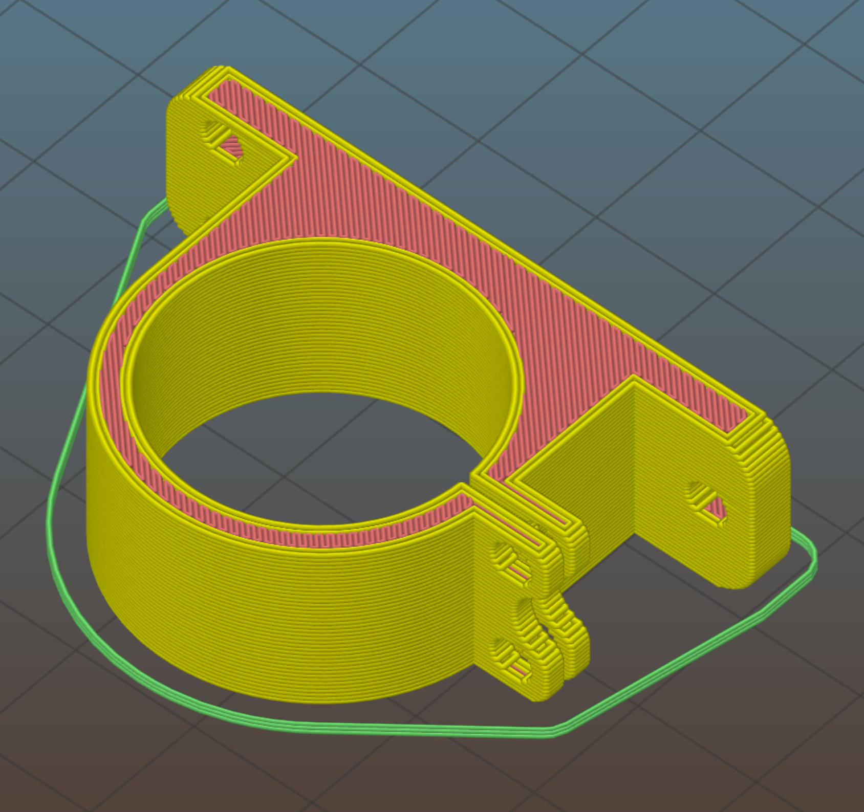
This is a really simple one that you basically never need to worry about, but should know is tweakable anyway. In the figure below you see a cross section of a sliced part with the infil in red and the outside layers in yellow. The shell thickness is the width of the outside wall as circled in the picture. You never need to worry about messing this unless you are printing without infill.
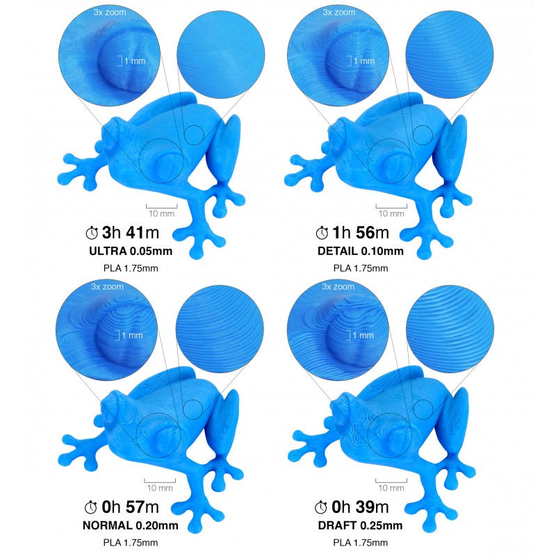
Layer Height
This is another fairly simple one. The reason it is below shell thickness is because it doesn’t have the power to compromise the integrity of the part. Just exponentially increase the amount of time it will take to print. If you have a small part, print it at 0.10-0.20, for really big stuff go up to 0.3-0.35. Low layer heights result in passes on the machine making high res parts take forever to print, print at low resolution whenever you can.
Scale
Just keep in mind that you can scale parts in the slicer without having to edit the actual design file. Allowing for quick customization for cosmetic parts like models, jewelry, or name plates.
Life in Plastic
Now onto a slightly less useful and interesting part of the lesson: Plastic choice. This can seem like a pretty mundane and useless decision to make during an engineering project, but it can make quite the difference.
PLA
Hassle: very low, 15$ per roll, non-translucent, glossy coloring
Is the cheapest filament or plastic by far. Always start with PLA to make sure the dimensions are right for a part you are making because it is the cheapest to replace. It also prints in the highest quality so cosmetic parts are best kept in the warm and fuzzy realm of printing with PLA. It is also the weakest mainstream printer filament and the easiest to melt. On a warm summer day it will get soft and lose form (don’t leave PLA in a warm car).
Additional bonus when working with PLA, it is biodegradable.
ABS
Hassle: pretty high, 23$ per spool, non-translucent, glossy coloring
ABS is much harder to print than PLA so parts that are supposed to look very smooth and professional should probably stick to PLA. But it is stronger for applications where high yield strength is necessary, it also won’t soften on a warm day, making it much more useful for applications involving nichrome wire or other instances of induced heating.
PETG
Hassle: pretty low, 27$ per spool, translucent, glossy coloring
PETG is a slightly modified version of the plastic that most bottles are made from, modified to be clearer and less brittle. It is stronger again than ABS, it cannot be overheated and made brittle, it can be sterilized, it is more impact resistant and it doesn’t soften under intense radioactive conditions.
Not that the cost increase may not seem like a big deal, it is really more the hassle increase due to how hard getting non-pla materials to stick is.
Weird Other Stuff
There are lots of other filaments with properties like even more strength than PETG, actually being clear, having embedded materials like wood, stone, or ceramics, etc… All of these are more expensive, will wear your machines down faster, and may require temps your machine can’t reach but they are all really cool. Do some research.
4. Design for manufacturing with CNC
One potential use for this class is to design a DIY cnc milling machine and this section is really only useful if you want to go that far or take the time to machine the parts we’ve been working on in this class. The process of DFM for milling is very different from 3D printing and ultimately much more difficult. I recommend getting a good idea of what cnc machining looks like and the way it works for this to be a really effective use of time.
How to design parts for CNC machining | Hubs
5. Epilogue
1. Introduction
What did we just do? Why did we do it? How can we do more? Well I can’t really answer those questions for you, but I do want to address some loose ends. While trying my best to help you discover if you like this process, what parts are your favorite, and how to get better at them. With plenty of time for safety.
Structure:
-
Introduction
- You’re already here.
-
General notes on machine safety
-
Materials and why researching them beforehand is important
-
Calibration and software implementation plus milling machine usage including basic CAM and tooling overview.
-
Final tidbits about how you can use an “okay” milling machine to make a better one.
2. Safety Concerns, Equipment, and Material Handling
Introduction to Safe CNC Operation
Something to keep in mind about machining is that it doesn’t compare too well to other forms of manufacturing available to makers. Processes like 3D printing, laser cutting, and even plasma cutting have far fewer variables to consider and can generally be nearly totally automated. The stakes of plasma cuts, 3D prints, and laser cutting failures are also generally fairly well constrained to poor performance and perhaps a small chance of fire or dangerous fumes. CNC milling or machining really raises the bar in this regard. The first things to consider are crashes which can happen at high speeds sending airborne shrapnell in near random directions. These occur when the cutting tool hits the wrong thing or isn’t moving too fast or isn’t moving fast enough. Everything in the equation can be a projectile: the material, the things holding the material, to the cutting tool or end mill, etc… Next the fumes and fire risks need to be accounted for. Lots of materials create hazardous dust or chips when machined that need containment.
3. A Note on Materials Handling and Selection
After a maker moves past exclusive use of 3D printers, they need to get into the habit of doing some basic research on any and all materials they are interacting with. Any spool on a 3D printer is a heavily vetted and researched item. The versatility of more advanced maker tools comes with costs. Almost anything can be machined but since most materials aren’t designed or sold for the sole purpose of CNC, it can take time to find the safety information you may need. And taking that time is always worthwhile.
Device Specifics
Laser Cutters
Many materials are available as thin, hard, sheets, but not all of them are well suited to laser cutters. Optimal choices for laser cutting will “vaporize” instead of melting under the extreme heat of the laser. Many plastics, especially those commonly used for food storage like HDPE and Polycarbonate melt and burn causing terrible quality parts and high risk of damage to a laser cutter and exposure to fairly toxic fumes[2]. It is always a good idea to make sure a material you want to laser cut is either on the “machine approved list of materials” or checking elsewhere that it has behavior similar to materials that are. The main dangers from laser cutters are eye damage, risk of combustion, and fume exposure. Most laser cutters are fully enclosed in a protective shield and have a vacuum pump pulling air out of the enclosure and filtering it. If a laser cutter is missing one or both of these it is a good idea to use a light respirator mask and laser rated shaded safety glasses. As for combustion risks, they are low if you have done your research on the material you’re cutting but it’s always a good idea to know where the fire extinguisher is located.
Plasma Cutters
Plasma cutters work by using accelerated super heated electrically ionized gas to cut through conductive metals. The limitation that the work pieces need to be conductive metals keeps things pretty simple here. The usual conductive metal suspects mild/tool Steel, Iron, Aluminum, Brass, Copper, and Stainless are all chemically stable and relatively safe. However, the interaction between the plasma and the metal is extremely dangerous. The bright arcs require welding visors to protect our sensitive eyes and the extreme heat and force of the plasma creates sparks and can create airborne chunks of superheated metal. When plasma cutting, ensure you’re wearing the proper safety equipment for welding the equivalent material. This includes, long sleeves to block from small burning fragments and from high UV exposure, a welding visor, and a respirator mask for fine dust and metal impurities made airborne by the heat.
Milling Machines
As mentioned before the big general safety concerns with CNC milling involve the end mills (milling machine specific drill bits for lateral and vertical cutting instead of just vertical) breaking during operation. This generally happens because the machine programmer (you) has fallen into one of thousands of pitfalls. For hobbyist machines, the speeds the fractured metal will reach can be a little frightening but solid eye protection like safety glasses or a clear face shield seriously mitigate the risks. The end mills are so lightweight that it’s unlikely the force from an endmill will cause more than a light bruise in a worst case scenario. If the “workpiece” or material being machined gets thrown, that would be substantially worse. It is important to make sure that any material being held down for machining is held strongly enough to withstand a serious blow from a mallet. A CNC can easily exert forces rivaling and even massively exceeding that hammer strike in extreme circumstances. The material hazards involved in CNC machining are generally derived from the way the CNC mill cuts material. The end mill takes small slices as it moves across the material and some materials, especially the soft ones, chip off in very small pieces. Aluminum chips will often be sized as splinters and very sharp while in stark comparison MDF or Medium-Density Fibreboard when milled often produces micrometer fine dust. The fine dust produced when machining MDF is dangerous because it contains high levels of formaldehyde and the fine particles can penetrate deep into the lungs. Another example of a material that’s dangerous to CNC machine is carbon fiber which produces small particles that are extremely sharp causing cuts inside the lungs and breathing tubes. Symptoms of inhaling this kind of dust are similar to the fairly well known lung disease: silicosis. Please wear a mask when cutting these materials at the very least.
With some of the scary stuff out of the way, the sheer amount of versatility offered by CNC milling is exciting. Mills can cut almost anything to pretty precise dimensions. But that means that materials with huge health risks associated with their use can slip by without a user taking the proper precautions. Always read about the materials you are about to cut beforehand and take proper precautions.
3. What’s next after hardware and electrical assembly?
Calibration and software implementation
This section is heavily reliant on information from part 2 of this coursework. Especially the materials in section 5 relating to information and communication structure of the milling machine. To briefly review that section, a mill’s electrical control system has a microcontroller and a computer that interact together to drive the CNC. The computer will have control software that will parse or interpret the CAM or toolpaths you’ve generated into serial or digital coordinate and machine status information for the controller. Many CNC controllers, especially older ones will be very “plug and play” because their hardware is built to be very proprietary. Newer CNC controllers will be built on more versatile platforms like the Arduino microcontroller which may require finding relevant source code and uploading it to the microcontroller. This article from Howtomechatronics (How to Setup GRBL & Control CNC Machine with Arduino (howtomechatronics.com) is an extremely useful guide for getting a handle on putting the right community made software on your Arduino powered CNC. The same article goes into how to calibrate a CNC machine too. This is useful because CNCs are very good at knowing how far they’ve traveled since they were powered up but pretty bad at figuring out their starting position. This is why CNC machines need to be “homed”. This is a prompted or unprompted slow motion of each axis in a defined direction until each gets to an origin position noted by a switch or other sensor of some kind.
Milling Machine Usage, CAM, and understanding tooling
Milling machines are awesome tools but they are slow and expensive. As you become a machinist you’ll begin to see exactly where milling machines work and what makes them more difficult and unruly. A lot of projects will take as much time to make tool paths/CAM for as they took to design. There are plenty of great introductory resources online to get started, I will link a few of the resources I’ve found the most useful and introduce the workflow of a lot of the machining operations I’ve done.
Fusion 360 CAM for CNC Beginners : 19 Steps (with Pictures) - Instructables
Fusion 360 CAM: Introduction & Toolpaths - Fusion 360 Blog (autodesk.com)
https://www.youtube.com/watch?v=Do_C_NLH5sw
CAM for Fusion 360 Tips and Tricks - Fusion 360 Blog (autodesk.com)
Most of the CAM you’ll write for starter CNC projects will be essentially 2.5 axis machining. Which is when you are only interested in a 2 axis sketch with various features having only a straight extruded depth. Think of parts that can be designed with only one sketch. Like a flat panel with a series of holes and a special outline. The lack of complex 3D geometry on these parts makes them comparably very easy to design CAM for.
Some Simple CAM tools and advice
For the majority of 2.5 axis milling there are three cam operations to consider. 2D Pocket, 2D Contour, and Engrave. 2D Pocket is the tool for clearing large amounts of stock without making a hole. It makes simple recessed parts quickly and efficiently. 2D Contour is for “cutting things out.”It creates long slots as deep as the stock. It is important when contour machining to enable the “tabs” option so the parts being machined don’t instantly fly out.
The path to a better machine
If you’ve decided to follow along on the hardware and electrical side of this project and have a small budget, but reasonably capable machine or if you’re considering taking the dive there is a long and reasonably interesting history of improving machines to follow. A very well designed machine tool should always be able to make a more accurate version of itself. This process is exactly how we are able to achieve the extreme precision of commercial machines today from the wood and stones our ancestors used.
If you’re interested in how this process worked historically, or in following along with with your own slightly optimised process check out a series of books by a famous DIYer called David Gingery who wrote a series of books on building a formidable machine shop with time and materials available in dumpsters and hardware stores.
Books: Build Your Own Metal Working Shop From Scrap - Hard Bound Edition (gingerybookstore.com)
Good Video Resource: The Best Gingery Lathe Video Series To Date | Hackaday
But what steps can I take with this specific device? Well that really depends on your time and creativity. The pen plotter really doesn’t need physical strength upgrades unless you want to build a bigger one. As mentioned in section 3, our pen plotter can fairly easily be turned into a somewhat capable milling machine. From there the mill should be able to make ⅛” parts out of aluminum which could be used to shore up the much less rigid 3D printed parts increasing rigidity and potentially feedspeeds. As mentioned in section 2, there are plenty of linear motion systems across all price ranges that could be implemented. The aluminum extrusion in combination with steel linear bearings would be a good combo for moving into more audacious CNC aluminum projects. Really, the only constraints on the upwards mobility of this system are time and money.
-
Motors for Makers: A Guide to Steppers, Servos, and Other Electrical Machines (index-of.es)
-
Note in this case “fairly toxic fumes” denotes NFPA fire rating of 1, with hazard identification noting toxic gases and fumes are released in burning but overexposure poses little likelihood of significant side effects. SciCron | MSDS | Polycarbonate Sheets (sctech.com)